9 Shear and Bending Stress in Simple Beams
Anahita Khodadadi
Before discussing shear and bending stress in simple beams, let’s watch video 9-1 (https://www.youtube.com/watch?v=SZM0kGBote4&t=1s) and review what the role of beams and columns are in a structural system and how they generally behave under dead and live loads. At the end of this video an online beam simulator is introduced that you can explore it further here.
Video 9-1: General behavior of beams and columns in a structural system
shear and Bending forces in simple beams
As we discussed in the previous chapters, the level of stress in a structural element depends on the applied external loads as well as its surface area or cross-sectional properties. Before addressing the shear and bending stress in beams, let’s overview the maximum shear and bending loads in a simple beam. The two diagrams below show the end reactions, maximum values of the shear load, and the bending moment in a simple beam supported by a pinned joint and a roller. The first diagram shows the maximum values for a beam under a point load, and the second shows the respective amounts for a beam under a uniformly distributed load.
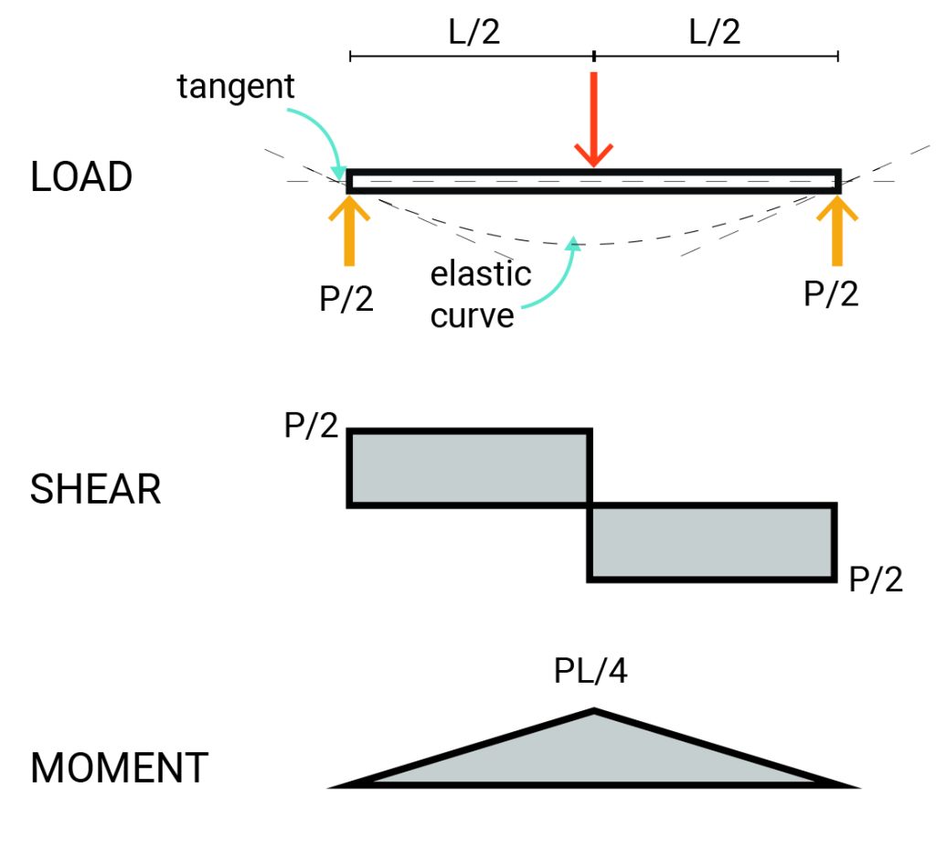
Maximums in a simple beam under a point load:
End reaction = P/2
Shear load = P/2
Bending moment = PL/4
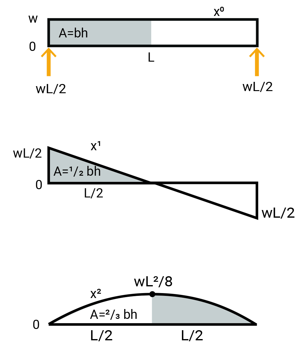
Maximums in a simple beam under a uniformly distributed load:
Equivalent point-Load = wL
End reaction R1=R2=wL/2
Shear load Vmax=wL/2
Bending moment Mmax=[latex]\frac{(wL)^2}{8}[/latex]
Figure 9-1: The end reactions, maximum values of the shear load, and the bending moment in a simple beam supported by a pinned joint and a roller
Sign conventions
As you can see, in the two diagrams, there are sign conventions for demonstrating the moment and shear in beams.
Sign Convention for Moment:
+ the top fibers in compression have positive curvature (holds water)
– the top fibers in tension have negative curvature (spills water)
Sign Convention for Shear:
+ the sum of the vertical forces to the left of the cut is upwards
– the sum of the vertical forces to the left of the cut is downwards
Maximum shear and Bending forces in different types of beams can be obtained by drawing a free-body diagram or referring to the AISC Steel Construction Manual and using the provided tables showing the shear and bending diagrams. Furthermore, online free beam calculators can be used to get maximum shear and bending values. BeamGuru and SkySiv are two free online platforms that can assist you in calculating beams.
Bending and shear stress in beams
Elastic bending stress
In a simple beam under a downward load, the top fibers of the material are compressed, and the bottom fibers are stretched. The change in fiber lengths at the top and the bottom of the beam creates strain in the material. This strain is proportional to the distance from the Neutral Axis. According to Hooke’s law, in a beam where the Modulus of Elasticity is constant across the section, the strain in the beam fibers is proportional to created flexure stress. Flexure stress in beams can be computed using the following equation:
[latex]σ=\frac{Mc}{I}[/latex]
Where:
M= Bending moment
I= 2nd Moment of Area
c = h/2 at extreme fibers of a symmetric section.
The above equation can be re-stated by replacing c/I with 1/S. Where S is the section modulus of the beam. Thus:
[latex]σ=\frac{M}{S}[/latex]
Shear stress
Shear stress is created by a shear force distributed across the section of the beam. Shear stress can be longitudinal or transverse. Just like flexure stress, this distribution is not uniform across the section. Shear stress can be calculated by either simply dividing the applied load by the area of the cross-section of the beam or using the following equation:
Shear stress will be maximum at locations where:
- V is high, for example, at the supports of the beam
- Q is high, for example, at the neutral axis
- b is low, for example, where the web width is thin
- I is low, for example, in less stiff sections
To stabilize beams against the shear stress, stirrups are included in reinforced concrete beams, or steel plates are bolted or welded to steel beams where shear stress is critical.
Review
The following image represents axial, bending, and shear stresses, as well as the corresponding equations for calculating the respective values.
Figure 9-2: Corresponding equations for calculating axial, bending, and shear stresses
Allowable Stress Design Method
There are different methods of designing beams. Allowable Stress Design is a unique design practice that requires designers ensure that the stresses imposed on the structures don’t exceed the elastic limit of the structural element. The allowable stress is determined by a factor of safety and the yield strength of the material. The allowable stress for different building materials is defined in building codes. For example, the allowable bending stress of structural steel is calculated by multiplying 0.66 and the steel yield stress. Likewise, the allowable bending stress of various species of structural wood is between 1000 to 600 psi.
You can design a beam by the following steps:
- Choosing a steel grade and allowable stress.
- Determining the bending moment either by solving a free-body diagram or referring to design manuals or online beam calculators.
- Calculate the section modulus (Sx) using the following equation:
4. Choose a safe section with a suitable Sx from the tables provided in design manuals
Beam Design – Example 1
A cantilever beam is loaded by a 0.4 k/ft uniformly distributed load along 8′ of its length as shown in the image below.

The beam end reaction, shear and bending diagrams are obtained using the the online beam calculator, BeamGuru. Find the suitable wide-flange steel or glulam timber section regarding the allowable bending stress limit.
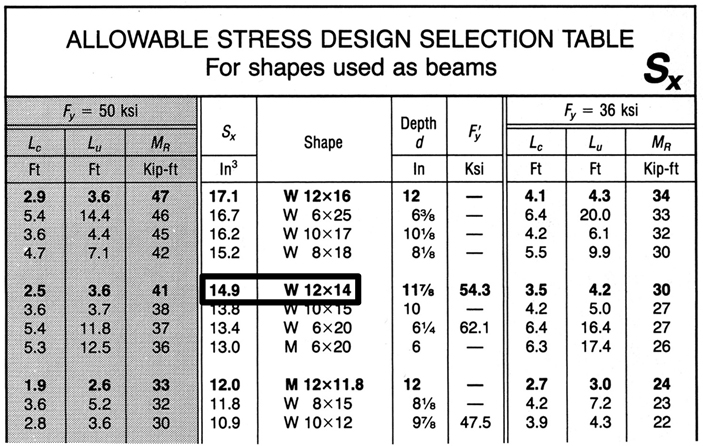
Solving for a wide-flange steel beam:
First, we select a steel grade whose yield stress equals 50 ksi.
Fy = 50 ksi Fb = 0.6 Fy
Referring to the steel construction manual, any wide-flange section whose Sx ≥ 12.8 in3 will be suitable.
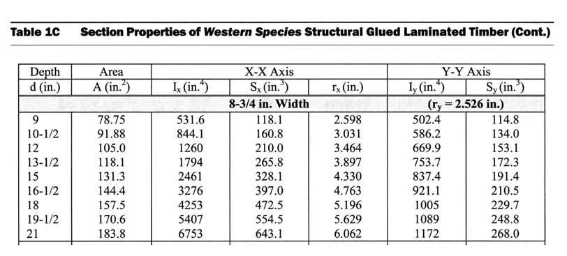
Solving for a glulam timber:
First, we select a glulam timber section with an 8 ¾” width and allowable stress of 1250 psi ( DF grade L3). Note that the width of the beam is usually determined based on the dimensions of the columns that hold the beam.