2 Forces and Vector Analysis
Anahita Khodadadi
Representation of forces
- Magnitude
- Direction
- Point of Application (position)

Figure 2-1: A vector is defined by magnitude, direction and point of application (position)
Forces may act on structural elements at one or multiple points. For example, a column that sits directly on a concrete slab applies a point load on a surface. Also, forces may be distributed uniformly (like the self-weight of a beam) or non-uniformly (like fluid pressure or snowdrift) along the length or surface of a structural element.

Figure 2-2: Distribution of load on a simple beam
The total magnitude of a distributed load can be represented as a single (resultant) load applied at the center of gravity. In two dimensions, the center of gravity is the same as the center of area of the distribution pattern.
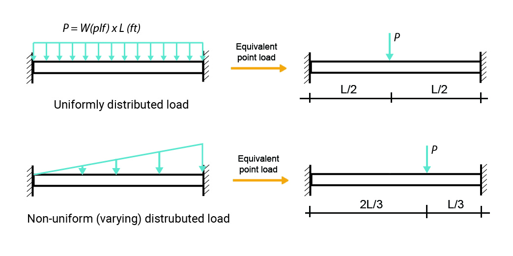
Figure 2-3: Equivalent point loads of two distributed loads
The image shown below represents different distribution patterns and the location of their center of area.

Figure 2-4: The center of gravity of different distribution patterns of loads
Characteristics of forces
Forces may cause:
- Tension: pulling apart.
- Compression: pushing together.
- Bending: applying equal and opposite couples in its own plane to an element; Or applying transverse forces to an element at some distance from its support.
- Torsion: twisting action from applying equal and opposite couples to the ends of a similar element in planes at a right angle to its axis.
- Shear: an action that tends to cause slipping of one part of an element on another.

Figure 2-5: Different characteristics of loads.
Note: The “Buckling” effect in long compression members will be discussed in Chapter 11.
Force systems
Force vectors may pass through a single point (concurrent) or be parallel (non-concurrent). Furthermore, force vectors may lay in a single plane (coplanar) or cannot be in a single plane (non-coplanar). Therefore, four different force systems can be identified:
- Concurrent – Coplanar
- Non-concurrent – Coplanar
- Concurrent – Non-coplanar
- Non-concurrent – Non-coplanar
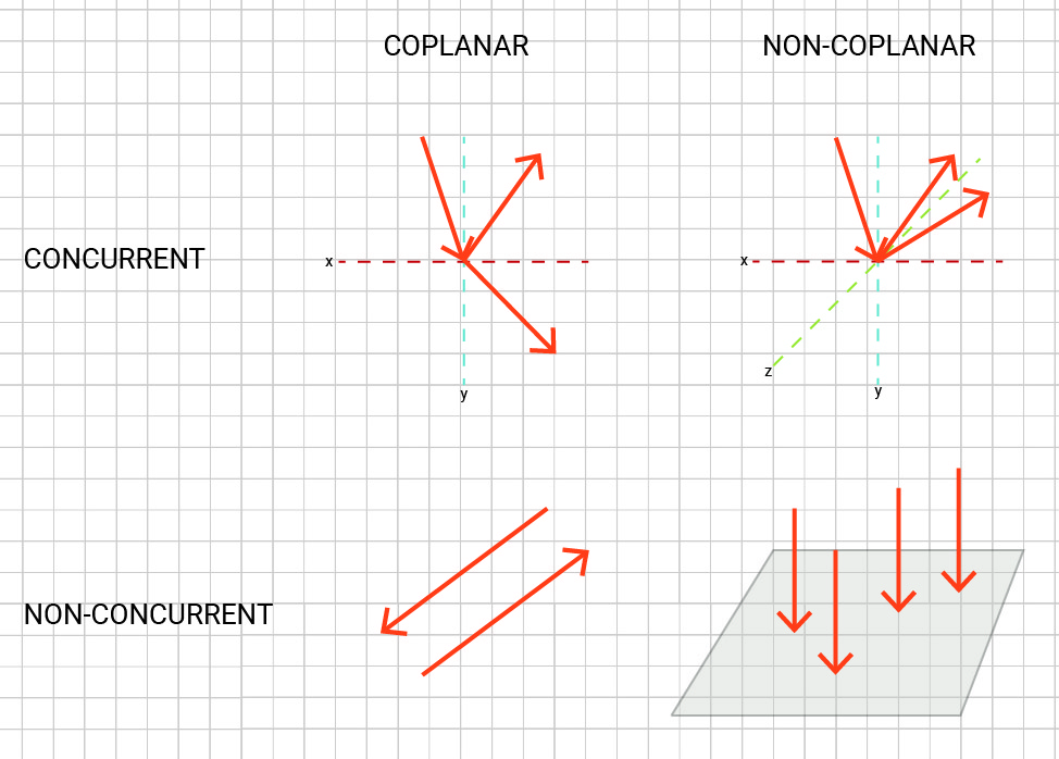
Figure 2-6: Different force systems
Force addition
1. Adding inline forces
If force vectors are all inline, you can simply add their magnitudes to find the resultant. You can see an example of linear addition in a tug-of-war rope contest.

Figure 2-7: When the two force vectors are applied in two different directions and have the same magnitude the resultant equals to zero.
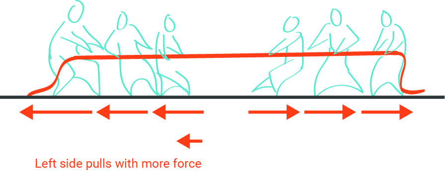
Figure 2-8: When the total of one set of force vectors are greater than the other set the resultant will be applied to the direction of the set with greater magnitude.
2. Adding orthogonal forces
Two orthogonal forces can be added together, simply by using the Pythagorean Theorem. The resultant equals to the hypotenuse. You may refer to “Intro to the Pythagorean theorem” at Khan Academy to review the Pythagorean equation.
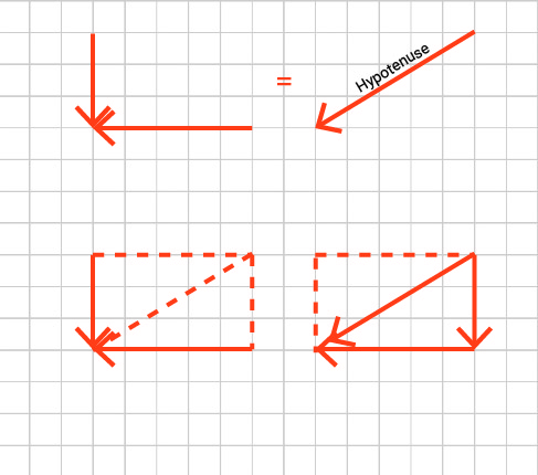
Figure 2-9: The resultant of two orthogonal forces equals the hypotenuse of the corresponding triangle
3. Adding two or more forces using graphic methods
You may add two or multiple force vectors by drawing either the force polygon or force parallelogram to find the resultant. In both cases, first, you should draw the force vectors to scale. Then, if you draw the force polygon, add the forces head to tail, and the resultant is the vector that closes the polygon tail to head.
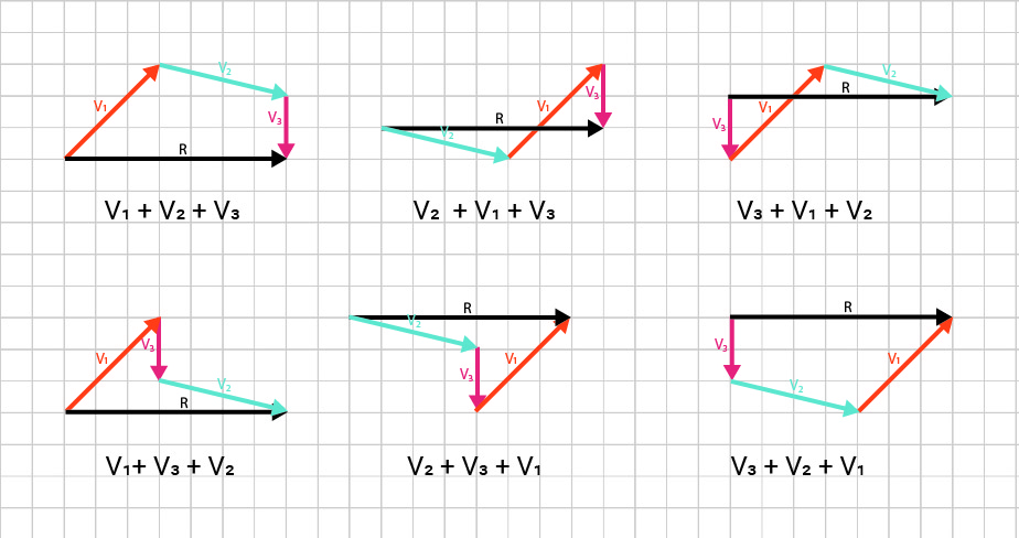
Figure 2-10: Adding two or more forces using the method of force polygon
You can draw the force parallelogram by pairing force vectors and drawing the diagonal of the corresponding parallelogram. Then, the resultant is the diagonal of the last parallelogram.

Figure 2-11: Adding two or more forces by drawing the force parallelogram
4. Adding two or more forces using an analytical method
When there are multiple force vectors, you may break each force vector into its horizontal and vertical components, sum all horizontal vectors together, sum all vertical components, and find the resultant of the orthogonal vectors. For example, F1, F2, and F3, shown below, are broken into their orthogonal components. Then, all horizontal components are added together, and all the vertical components are added together. Finally, the resultant of the two horizontal and vertical vectors can be calculated by using the Pythagorean theorem.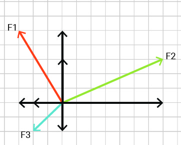
ΣFx = F1x + F2x + F3x , ΣFx = -3 +7-2= 2
ΣFy = F1y + F2y + F3y , ΣFy = 5 +3 -2 = 6
Ftotal = √(22 + 62 )= √40 = 6.32
If you would like to review the fundamentals of vectors analysis, see Khan Academy’s module on Vectors.
The basics of orthogonal triangle trigonometry are represented below. Moreover, you may review right triangles & trigonometry at Khan Academy.
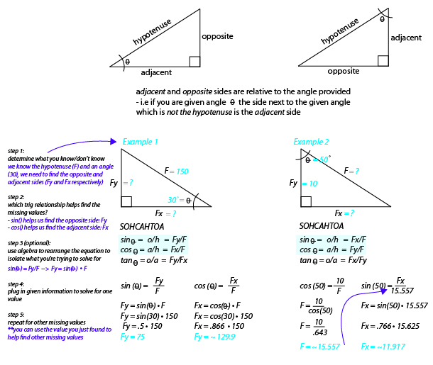
Figure 2-12: Basic review on solving orthogonal right-angle triangles
Equilibrant
The equilibrant is a vector that has the same size as the resultant but is in exactly the opposite direction. Equilibrant balances the forces and makes them not push.
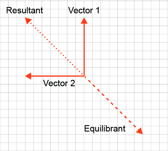
Figure 2-13: Resultant vs. equilibrant
Watch the following video in “Equilibrium of a Point” (https://www.youtube.com/watch?v=a2IX52UlCWE) to learn what condition must a point in a structure satisfy to remain in equilibrium.
Video 2-1: Adding force vectors and equilibrium of a point
Topics for critical thinking
- We want to hold a bucket of 50 lbs by a rope pulling it from two sides. How much is the tension force in each side of the rope?

- Do you think that you can flatten a clothesline?

(Image source: Clothes Line, https://www.flickr.com/photos/bmitd67/5045044902)
- Play around vector addition using PhET interactive simulator provided by the University of Colorado Boulder.
- Practice application of principles of vector addition using the Vector Guessing Game Interactive.
- What is the difference between deflection and bending?
