4 Catenary Cables and Arches
Anahita Khodadadi
Catenary Cables
Geometry and basic principles
Cables are structural elements that can hold a great amount of tensile force with a relatively small cross-sectional area. Thus, cables are considered highly efficient structural components, and one of the most economical ways to span a large distance is employing a cable system. However, cables can resist only axial tensile forces and not any compression or bending moment. Since cables have a minimal cross-sectional area, they are flexible elements and change their shapes under different load conditions to reach equilibrium. For example, a cable under a simple point load forms two straight lines meeting at the point of application of the load. Cables under a uniformly distributed load sag in a catenary shape or a parabola.
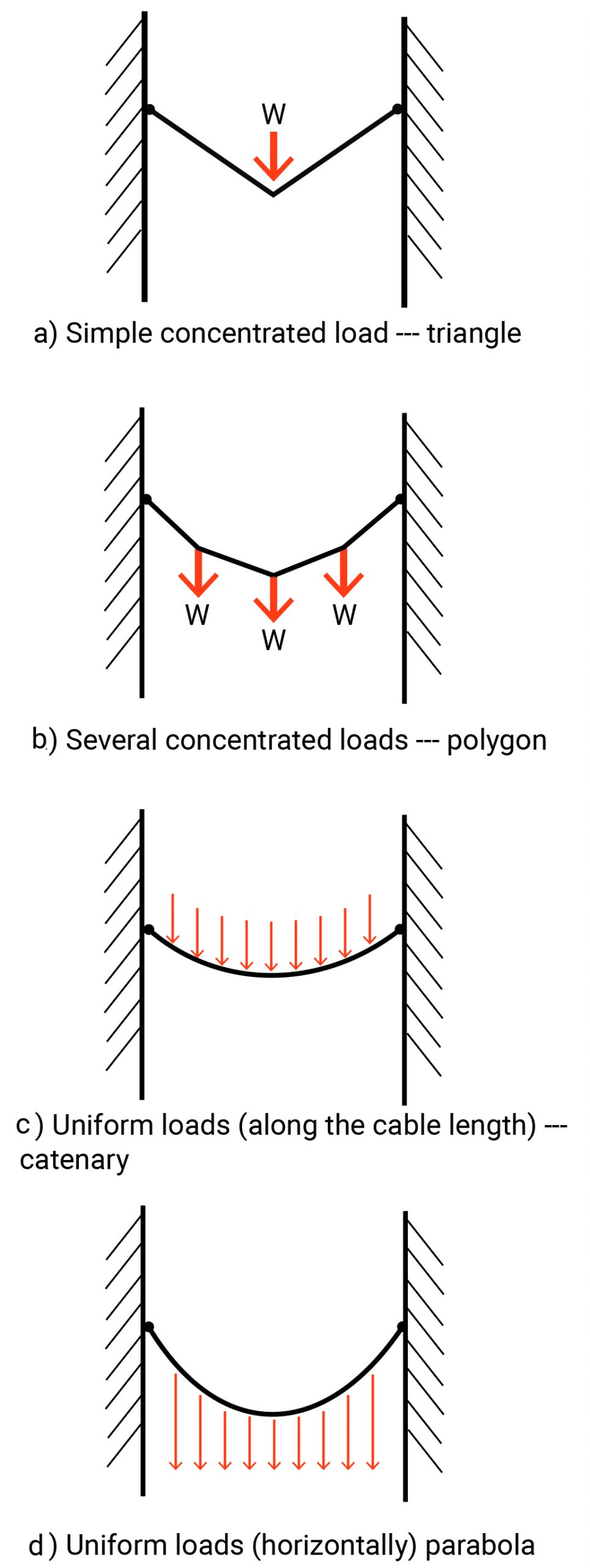
Figure 4-1: Forms of cables under different load conditions
A catenary is a funicular shape for an unloaded cable and is determined solely by the self-weight of the cable, which is uniformly distributed along its length. A catenary cable sags under such a uniformly distributed load along its length, and transfers the load to its two supports in equal shares.
In contrast, a parabola is a funicular shape of a suspension cable loaded uniformly across its span. Although, the self-weight should be insignificant compared with the load to give a pure parabola shape to a cable.

Figure 4-2: A catenary cable vs. a cable with a parabola shape
Where the sag-to-span ratio is greater than 5, the two shapes are nearly identical, and mathematically, it is simpler to utilize a parabola for analysis.

Figure 4-3: The difference of a catenary shape and a parabola
The load and the sag-to-span ratio determine the tensile force in a cable. Thus, in catenary cable structures, the sag-to-span ratio is a primary structural design consideration. The sag-to-span ratio influences:
- Cable forces: they are inversely proportional to sag.
- Inward thrust
- Cable length and the cable diameter: as the cable length decreases, a greater diameter is required.
- The column or tower (mast) height and the compressive forces

Figure 4-4: The relation between the horizontal thrust and the sag-to-span ratio in a loaded cable
For a uniformly loaded parabolic cable, the optimum sag-to-span ratio is 33%.
Most of the suspended roof structures (where cables are used for building the roof) have a sag-to-span-ratio of 1:8 to 1:10.
Classification of the topology of cable structures
Classification of cable structures allows a better understanding of their behavior and the determination of suitable design techniques. Cable structures can be classified into three main categories:
- Single-curvature structures: A series of parallel catenary cables span between primary supports and hold a deck directly or hold a series of secondary vertical cables that carry the deck. A well-known example of this type of cable structure is the Dulles Airport Terminal. There are several suspension bridges where single-curvature cables shape the main configuration of the structural system. Akashi Kaikyo Bridge in Japan, Nansha Bridge in China, Verrazzano-Narrows Bridge in New York, Golden Gate Bridge in San Francisco, and Mackinac Bridge in Michigan are suspension bridges with single-curvature configurations.
- Double-cable structures: Some stabilizing cables are added below the primary suspensions cabless to resists the wind uplift. In Utica Memorial Auditorium, two layers of pre-tensioned cables span between an outer compression ring and a central tension ring.
- Double-curvature structures: Some stabilizing cables are added below the primary suspensions cables to resists the wind uplift. Similar to a saddle shape, the primary suspension cables sag between the supports and cover the span. The stabilizing cables run in a perpendicular direction with an opposite curvature. The roof of Dorton Arena in Raleigh is composed of a double-curvature cable structure and two compressive arches.
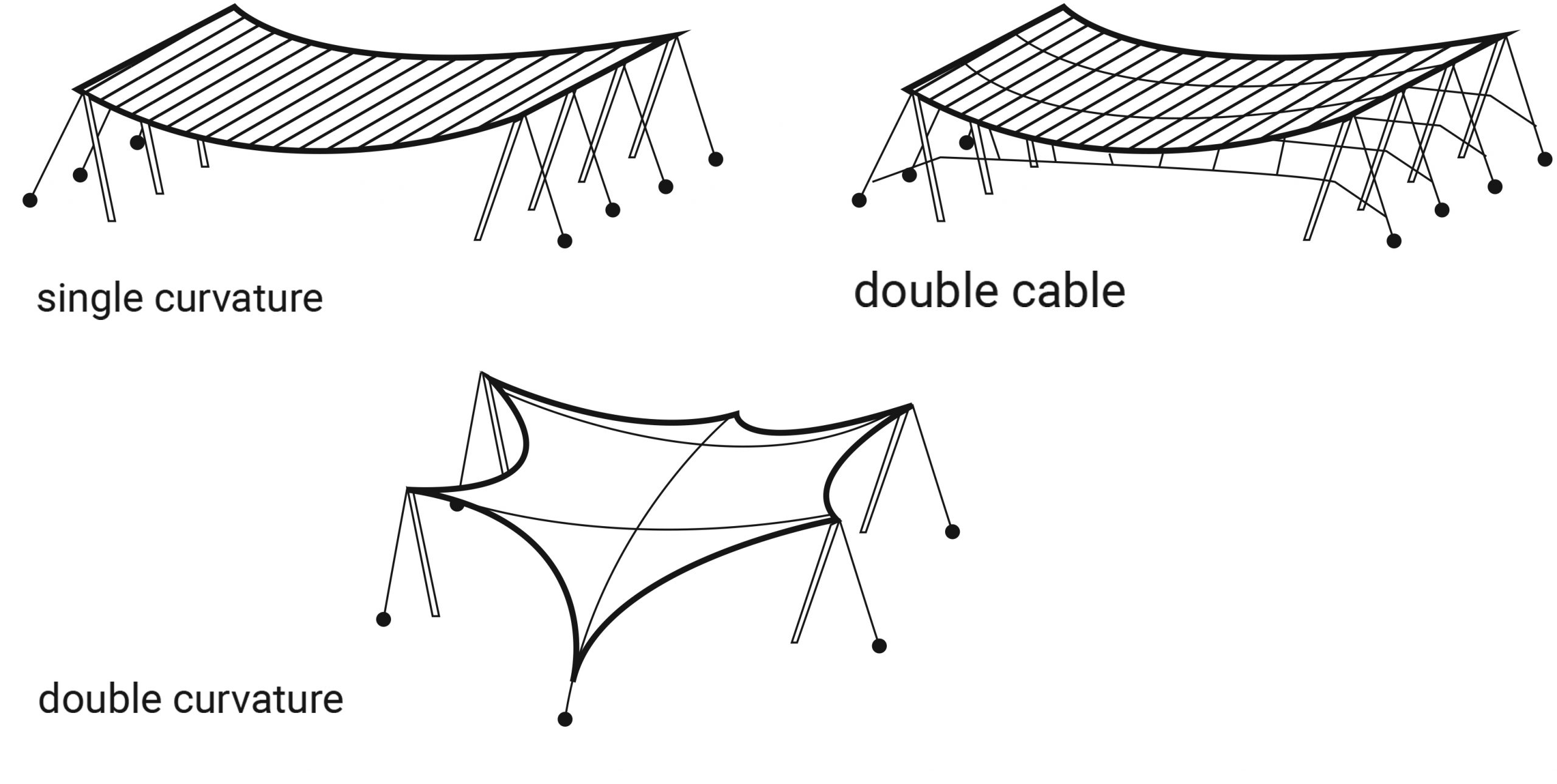
Figure 4-5: Different types of cable structures
Materiality
Cables can be of mild steel, high strength steel, stainless steel, polypropylene, fiberglass, and carbon. High-strength steel cables are the most reliable and economical material for linear tensile members. Structural cables are made of a series of small strands twisted or bound together to form a much larger cable. Usually, the steel used in cable structures has breaking stresses that exceeds 200,000 psi which is 4 times the strength of structural steel sections common in building construction.
The principal elements of a cable-supported structure
A cable-supported structural system includes main cables, vertical supports or towers, anchorages, and stabilizers. Vertical supports may be masts, diagonal struts, walls, vertical or sloping piers. Vertical supports keep the cables above the ground and provide essential reactions.
Since the main cables are not placed vertically, the carried axial forces have a horizontal component. This horizontal thrust should be resisted by a suitable anchorage system. Therefore:
- The main cables of a suspension bridge may be attached to the ground and be earth-anchored.
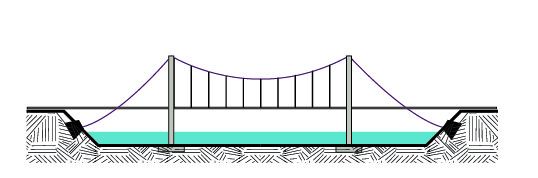
Figure 4-6: An earth-anchored suspension bridge
2. In a self-anchored suspension bridge, the main cables may be attached to the end of the road deck.
Figure 4-7: A self-anchored suspension bridge
Another type of self-anchoring bridges is where multiple primary cables hold the deck and their connection pattern may resemble a harp, a fan, or a star.
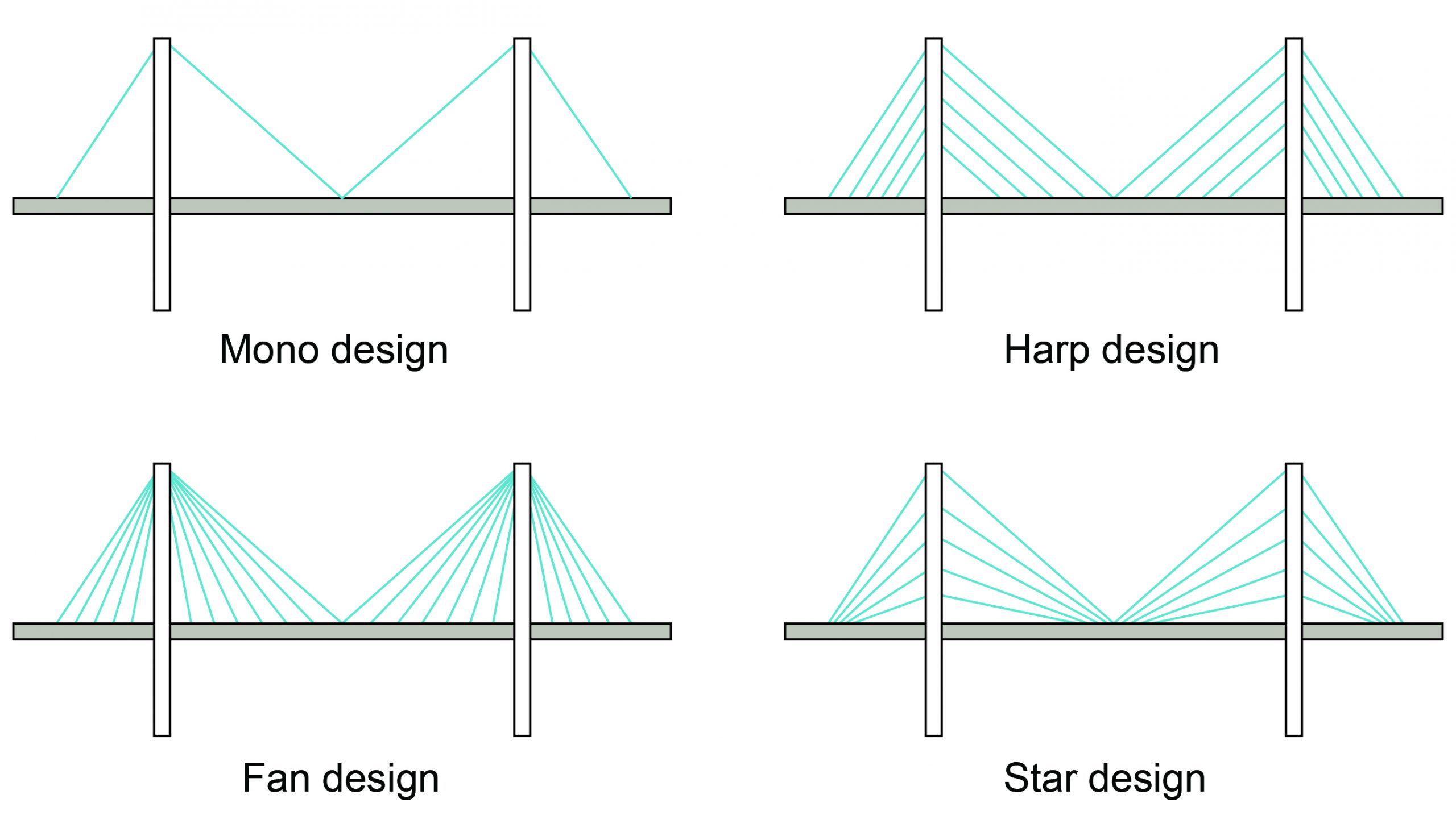
Figure 4-8: Different patterns of connecting cables to the bridge deck
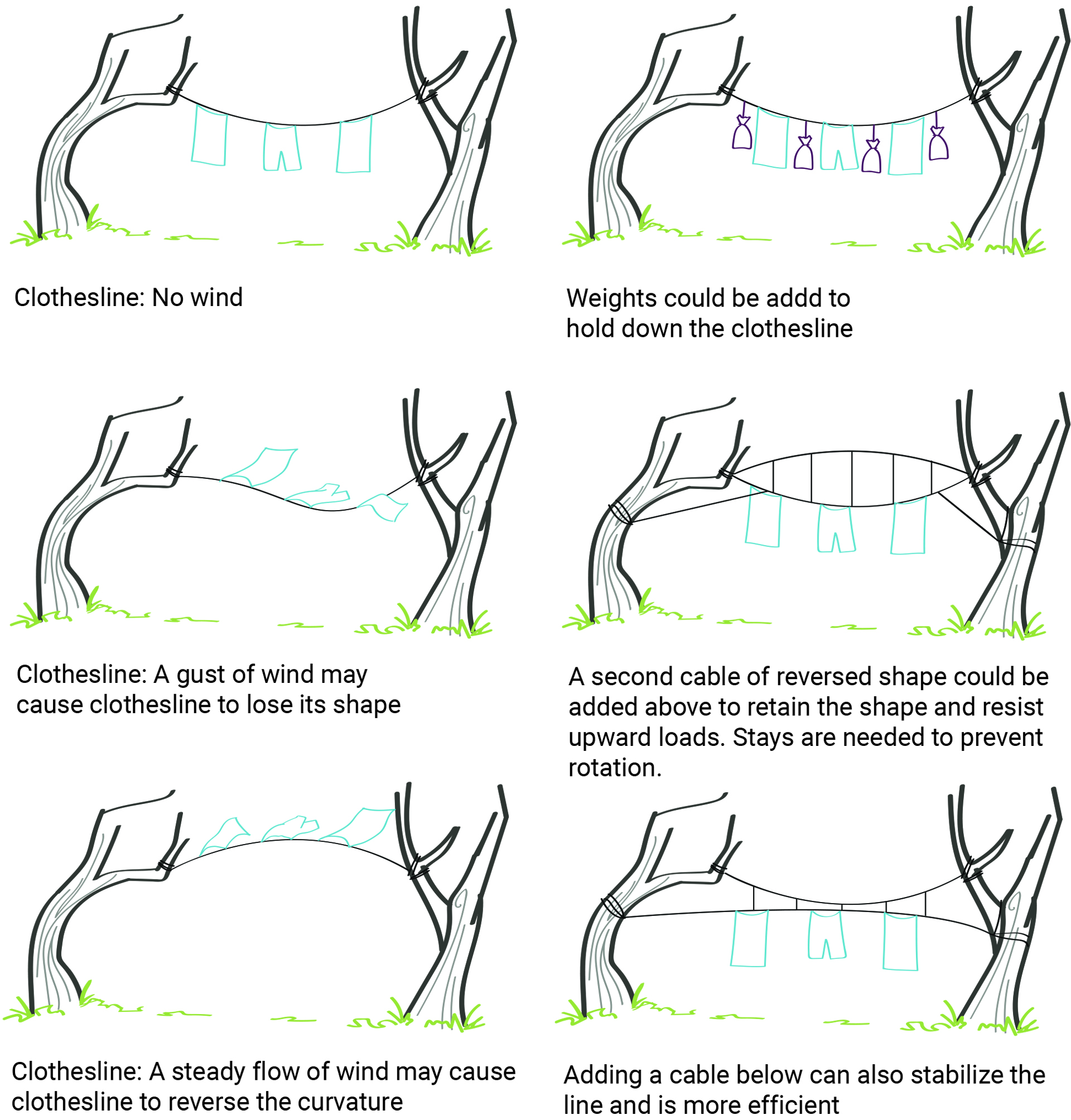
Usually, designers use the dead weight of the roof/deck construction, a rigid surface that includes the main cables, a set of pre-tension cables with reverse curvature from the main cable, or restraining cables to stabilize cable-stayed structures. In the Dulles Airport Terminal, you can see some of these thoughtful ideas are applied to stabilize the cable-stayed roof structure.
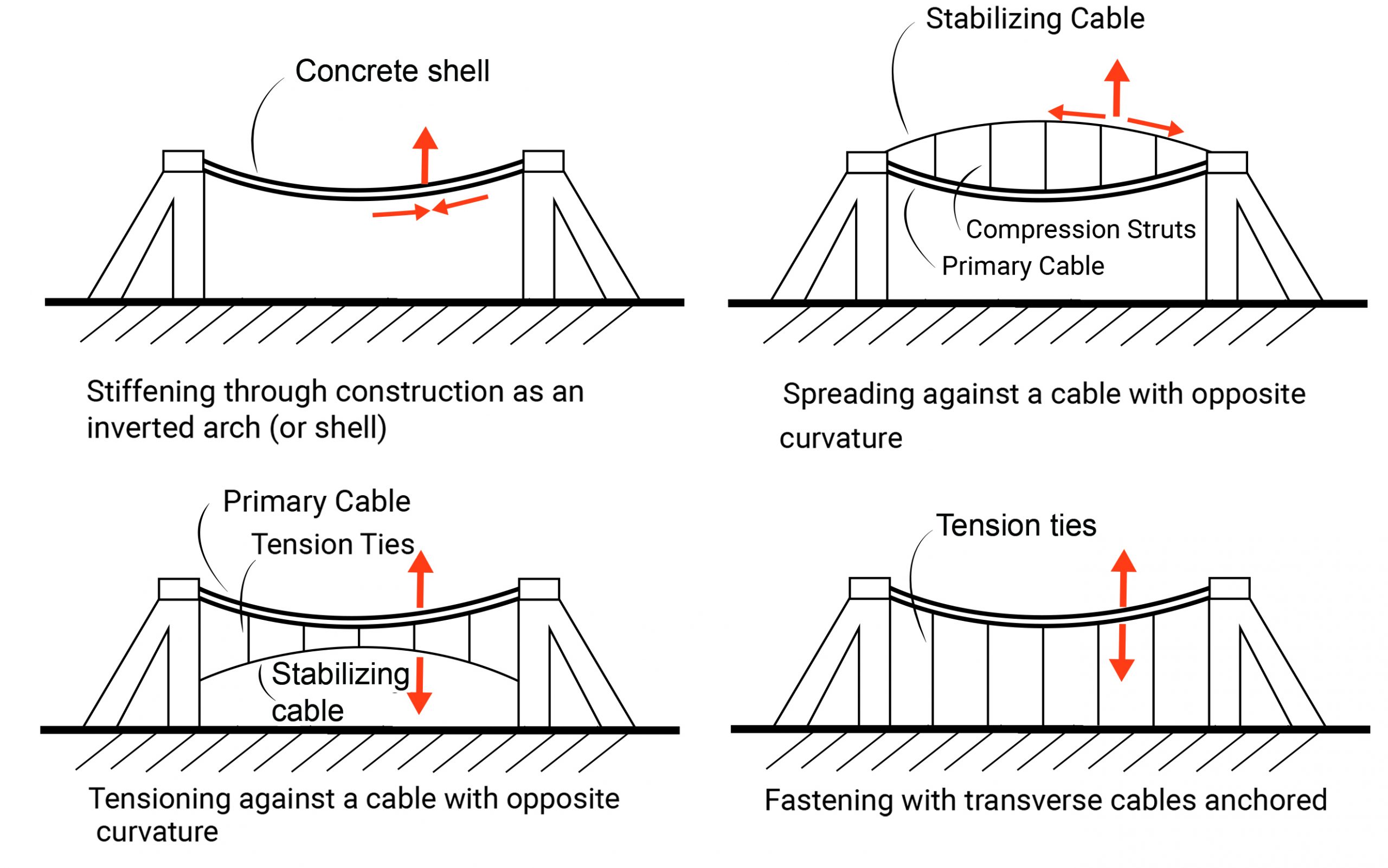
Figure 4-10: Different ideas for stabilizing a cable-stayed roof structure. Note: Primary cables carry gravity loads and secondary cables stabilize the bridge against uplift forces.
Furthermore, stabilizers are employed to prevent structural destruction due to probable resonance. All materials have a natural molecular vibration or frequency range. If an outside force acts on a material within that natural frequency range, it causes the outer and inner forces to become tuned, and the material undergoes destruction.
Tacoma Narrows Bridge was a suspension bridge in the state of Washington that collapsed on November 7, 1940. The bridge collapsed because normal speed winds produced aeroelastic flutter that matched the bridge’s natural frequency. The collapse of the bridge was recorded on film by Barney Elliott, owner of a local camera shop.
In addition to analyzing the principal elements, a cable-supported structure should be finely studied regarding corrosion protection, in-service inspection, fire resistance, and effects on the structure due to the removal and replacement of cables during the lifetime of the structure.
Catenary Arches
Arches have been used in many subtle historical constructions. A catenary arch redirects forces into axial compression to span an opening. How do arches work?
As you learn from the lecture, a funicular arch is the inverted compressive equivalent of a suspension cable. In the 17th century, Robert Hooke studied the catenary forms of a hanging chain and discovered this principle. A catenary arch is subject to carry only axial compression and not bending forces.
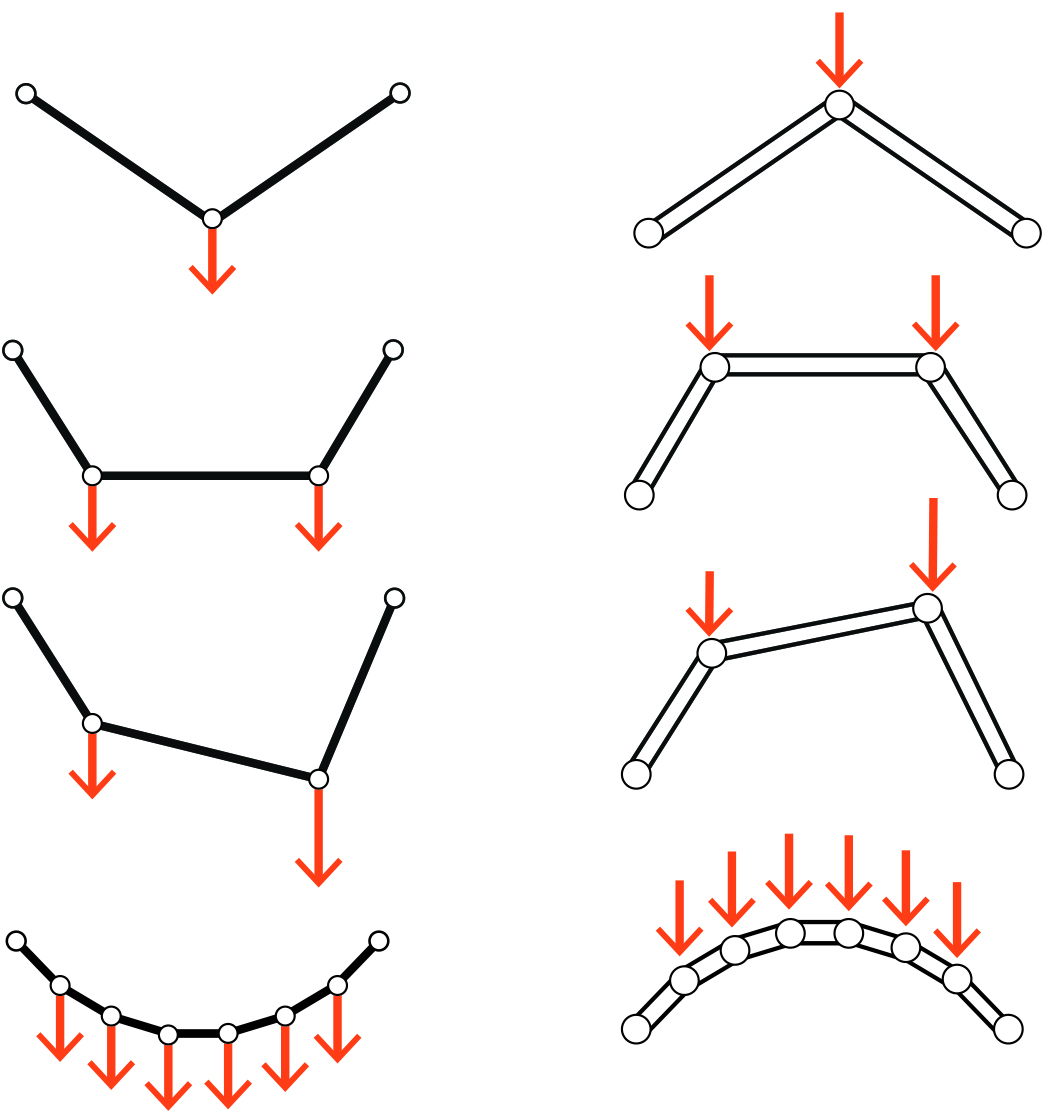
Figure 4-11: The relation between a funicular arch and its corresponding funicular cable
Suppose the applied load is distributed uniformly along the length of an arch. In that case, the funicular arch should be equivalent to an inverted catenary cable to carry the loads only in axial compression. On the other hand, if the load is distributed uniformly along the span, the form of the funicular arch should be equivalent to a parabola.

Figure 4-12: A catenary arch vs. an arch with a parabola shape
If the magnitude and direction of the forces on a cable change, the resulting form of the cable changes to adjust to the new load condition and to remain in tension. However, arches inherently cannot be adjusted to the new load condition. If the loading changes the shape of the arch will no longer be funicular. Thus, arches and related structural systems usually experience compression and bending at the same time (similar to thin shells).

Figure 4-13: The relation between the horizontal thrust at the supports of an arch and its rise-to-span ratio
Rule of thumb to determine the proportions of structural components
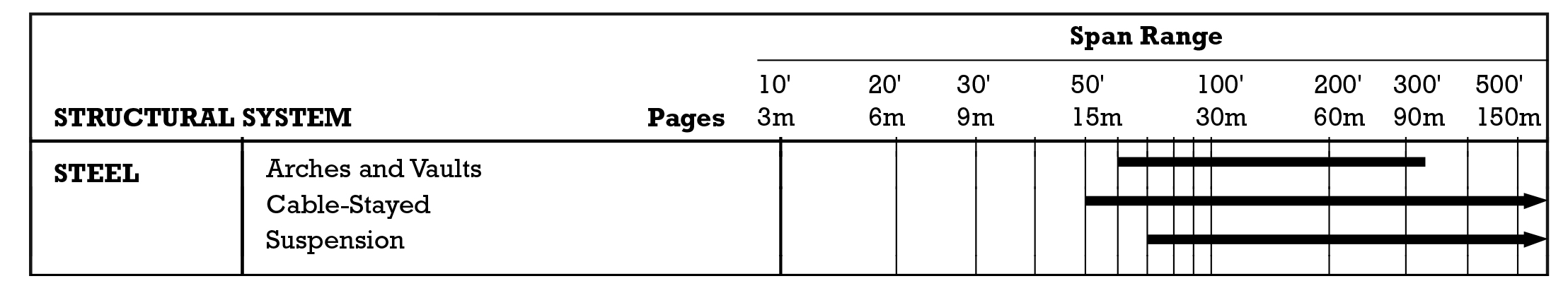
The economic span for using a cable-stayed structure is between 50 and 500 ft. The suitable sag to span ratio is better to be around 1:10. The cable diameter can be 1:8 into 3 ft based on the loads and span.
Table 4-1: The economic span of a cable-stayed structure [2]
