10 Deflection in Simple Beams
Anahita Khodadadi
Building structures are expected to be designed for strength, stability, and serviceability. Therefore, when designing a structural system with suitable strength, designers should consider tension rupture, compression crushing, and flexure in structural components. The stability of structural systems should be addressed by controlling buckling in columns and lateral-torsional buckling in beams. Finally, a structural system is expected to be not only a safe construction but also provide the building occupants a sense of comfort. Moreover, the structural system should not impact the durability of other building assemblies, such as interior finishing. Thus, beam deflection, building story drift, and cracking should be prevented in structures. In this chapter, the deflection of beams is discussed.
Definition and principles
In a simple beam, the compressive and tensile forces above and below the neutral axis result in a shortening and lengthening of the longitudinal fibers respectively above and below the neutral axis. This effect causes bending in the beam and displaces the beam fibers from their original positions. By definition, deflection is the displacement of the beam from its original horizontal position when subjected to loads. Various guidelines have been derived to determine maximum allowable deflection limits.
Typically, a floor system with a live load deflection in excess of L/360 will feel bouncy or crack plaster. The maximum deflection in a simple beam under a point load can be calculated using the following equation:


The maximum deflection in different types of beams can be obtained by drawing a free-body diagram or referring to the AISC Steel Construction Manual and using the provided tables showing the shear, bending, and deflection diagrams. Furthermore, online free beam calculators can be used to get maximum shear and bending values. ClearCalcs, and SkySiv are two free online platforms that can assist you in calculating beams. The following image shows a solved beam using the ClearCalcs online tool.
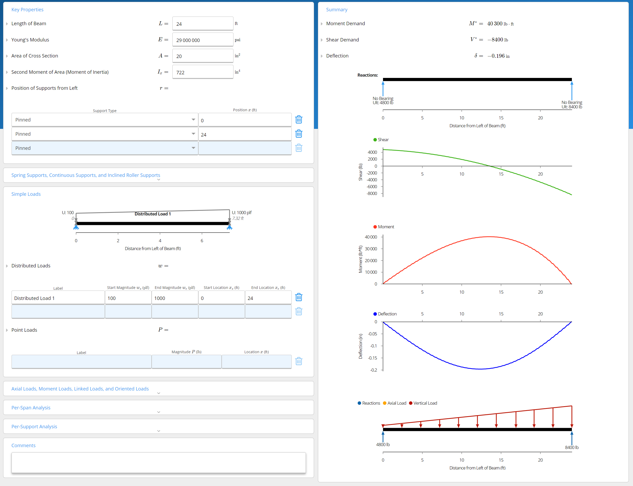
Figure 10-3: Diagrams of shear stress, bending stress and deflection of a beam solved by the ClearCalcs online tool
By “superposition,” equations can be added for combination load cases. Care should be taken that added equations all give deflection at the same point, e.g. the centerline.
Note that if beam lengths and load (w) are entered in feet, a conversion factor of 1728 in3/ft3 must be applied in order to compute deflection in inches.
Understanding the relationship between the maximums
A series of relationships between forces and deformations along a beam can be helpful in analysis. Using either the deflection or load as a starting point, the following characteristics can be discovered in a simple beam under a point load applied to the mid-span:
- Maximum slope occurs at the ends of the beam
- The point of zero slope occurs at the centerline. This is the point of maximum deflection.
- The moment is positive for gravity loads.
- Shear and slope have balanced + and – areas.
- Deflection is negative for gravity loads.
The following characteristics can be discovered in a cantilever beam under a point load applied to its free end:
- The fixed end has the maximum moment but has a zero slope and deflection.
- The free end has the maximum slope and deflection but a zero moment.
The idea of Pre and post-stressing
One of the methods of making the reinforced concrete beams more efficient is using pre-stressing or post-tensioning, where a beam is permanently loaded in a way that stresses are built up in the member opposite to those developed by the external loads.
Post tensioning
For constructing a post-tensioned concrete beam, a framework is positioned, hollow sheaths containing unstressed cables are draped into place, and concrete is cast around the sheaths. After the concrete is cured, cables are tensioned by jacks at each end of the beam. When the framework is removed, the cable force is maintained by permanent anchors at each end.
Video 10-1: Post-tensioning system (https://www.youtube.com/watch?time_continue=1&v=eQ2fJEbvJBs&feature=emb_logo)
Pre-tensioning
In a pre-stressed concrete beam, steel cables are pre-tensioned between abutments using hydraulic jacks. Then, concrete is cast around pre-tensioned cables and allowed to cure. After the concrete is cured, cables are cut. Cables apply a compressive force to the ends of the beam at the bottom level. This causes the beam to bow up, and the created curve offsets the deflection once the beam is loaded.
Video 10-2: Pre-stressing a reinforced concrete slab (https://www.youtube.com/watch?time_continue=1&v=0z6gjjrSn0M&feature=emb_logo)
Topics for critical thinking
- Consider the location of the maximum deflection in beams, and explain which of the following beams is designed better?
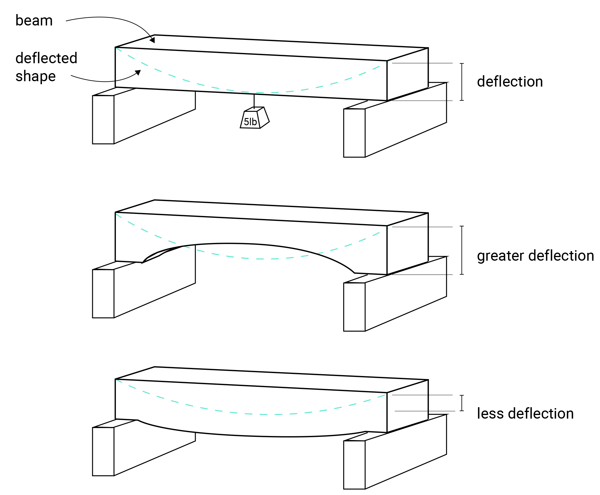
Figure 10-4: Deflection in beams with different longitudinal shapes
