5 Trusses
Anahita Khodadadi
Geometry and basic principles
A truss represents a structural system whose elements are two-force members arranged in a planar triangular pattern and each member is either in tension or compression. The stability of a truss relates to its triangular shape. By definition, trusses have pinned joints and concurrent straight members and have to be loaded through their joints. This means that a frame structure with rigid joints is not considered a true truss. A Vierendeel frame is a well-known example of such a frame structure with rigid joints that cannot be considered as a true truss. In reality, a combination of bolting and welding is used to make the joints. Thus, joints become somewhat rigid connections that develop some moment resistance. Bending stresses, however, are often relatively small in comparison to those resulting from tension and compression.
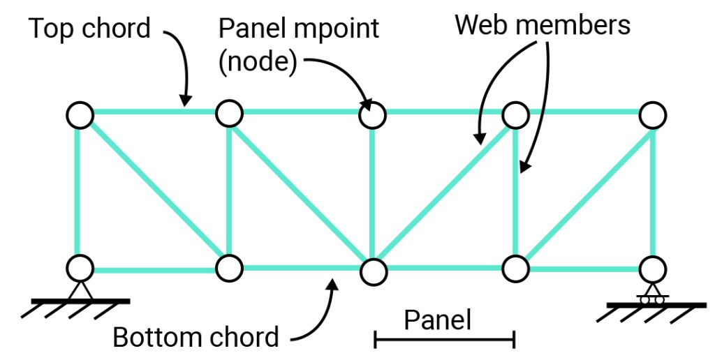
Figure 5-1: Truss components’ nomenclature
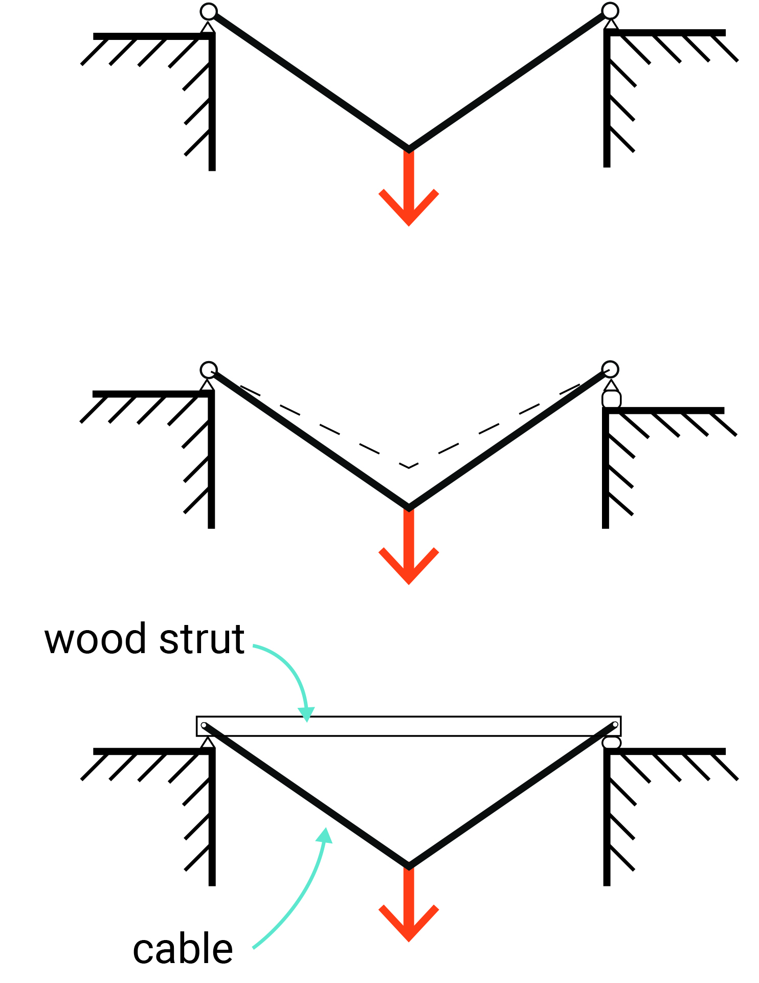
Figure 5-2: The process of creating a simple truss module
This simple truss module is used to form complex forms of trusses where compressive elements are made of rigid struts (double lines), and tensile strengths are substituted by cables (single lines).
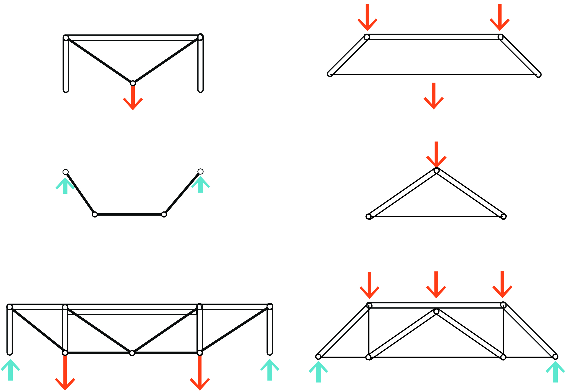
Figure 5-3: A simple truss module can be used to form complex forms of trusses where compressive elements are made of rigid struts (double lines), and tensile strengths are substituted by cables (single lines).
Stability and determinacy in trusses
The first step in designing a truss is the analysis of its stability, its internal and external determinacy or indeterminacy. Stability in trusses refers to their ability to maintain their configuration while resisting loads applied to their joints. For a stable truss the equilibrium conditions (∑Fx= 0, ∑Fy= 0, ∑M= 0) are always satisfied regardless of the position or direction of the applied loads. In other words, if we can find even a single loading case for which the equilibrium equations cannot be satisfied, then we must conclude that the truss is unstable.
A stable truss may be either statically determinate or indeterminate. When a member is added to a stable truss or the number of support reactions is greater than the number of equilibrium equations, the truss is still stable. But if the number of unknown forces is greater than the number of equilibrium equations, the truss is considered statically indeterminate. There is a nifty method for the identification of stability and determinacy in trusses.
For:
• k, k= 2j-r
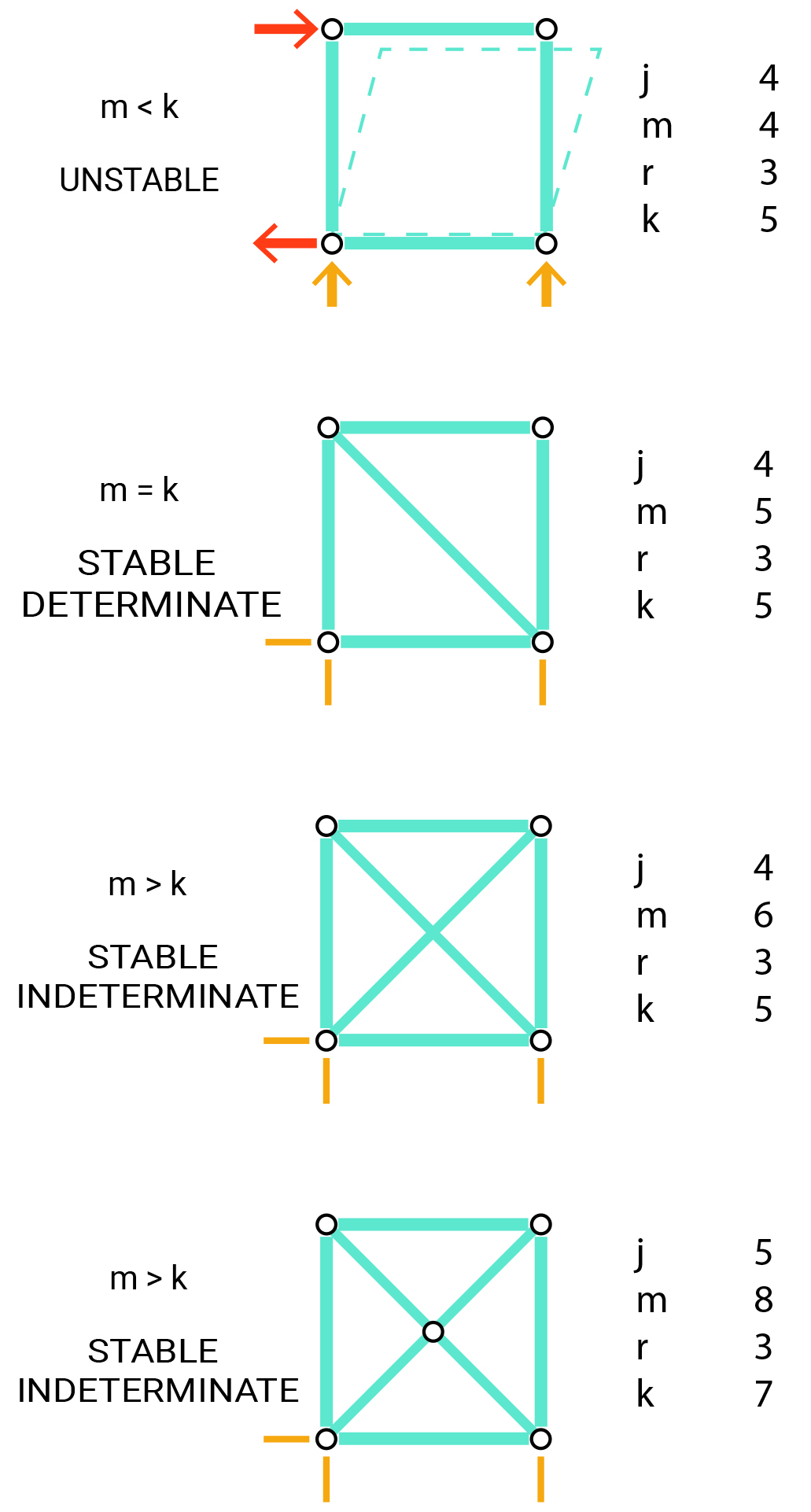
Figure 5-4: Identification of stability and determinacy of trusses by using the k= 2j-r equation
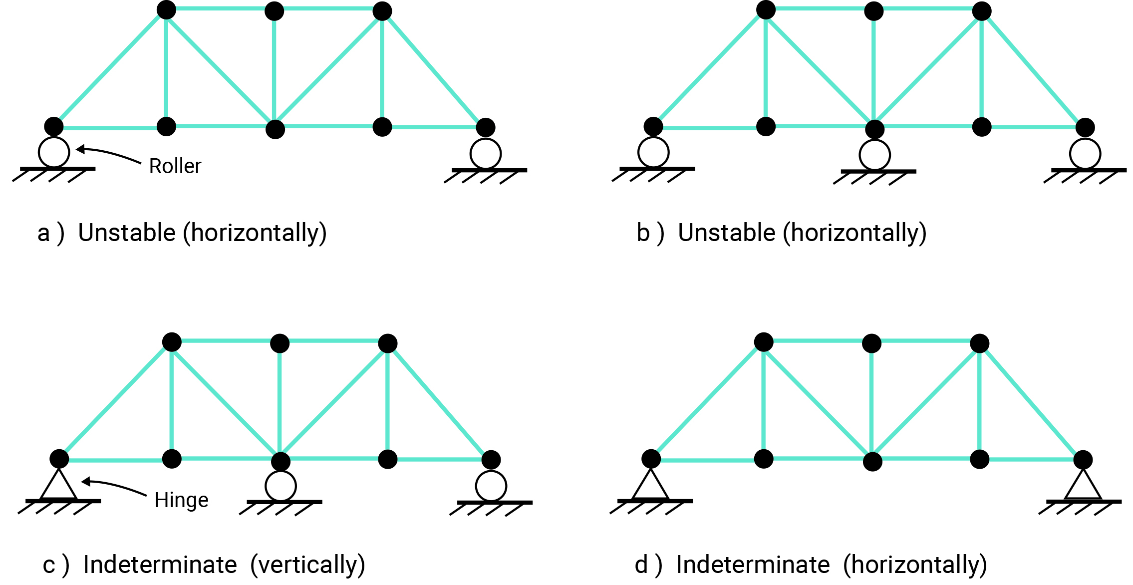
Figure 5-5: Examples of indeterminate or externally unstable trusses
Zero-force members
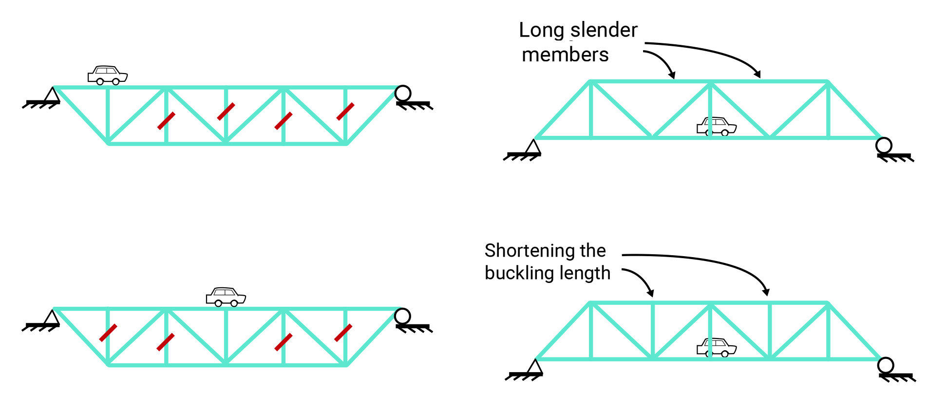
There are members in trusses that are designed for moving loads. Thus, depending on the position of the external load, they may carry no load. These members are often referred to as zero-force members. Moreover, sometimes zero-force members are included in the configuration of a truss to split long slender compression members into two or shorter members (brace the long members) and stabilize the truss against buckling. These bracing members often carry no load.
For trusses to be in the state of equilibrium, the sum of the forces acting at each joint must be zero. By placing and rotating the coordinate system at a joint, we can study if there is only one force acting in either x or y-direction. That single force must be zero, and the member associated with it is a zero-force member.
Truss analysis by the method of joints
Resolution of joints is one of the first methods for truss analysis. This method involves the following steps:
- Solve reactions (all external forces)
- Inspect for zero force members (T’s & L’s)
- Cut a Free-body-diagram (FBD) of one joint. A free-body diagram of a joint consists a diagrammatic representation of the joint and all the forces acting on it.
- Show forces as orthogonal components
- Solve with ΣFx and Σ Fy (no Σ M)
- Find resultant member forces (Pythagorean Formula)
Example:
Solve the following truss using the method of joints.

Step 1: Check for horizontal, vertical and rotational equilibrium
ΣFx= 0 2- Rax = 0 Rax=2 kips
Σ Fy = 0 Ray + Rc – 5 = 0 Ray + Rc = 5
ΣM= 0
ΣM @A:
-Rc × (36+36) + 5 × 36 + 2×27 = 0 Rc = 3.25 kips
Ray = 5 – 3.25 = 1.75 kips
Step 2: Any zero-force member? No
Step 3: Solving joints by decomposing force vectors to their horizontal and vertical components
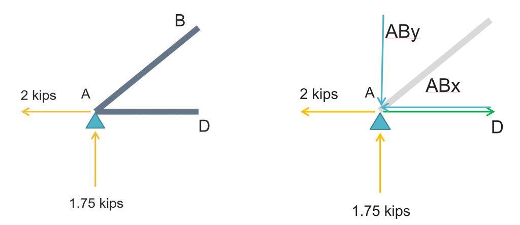
ΣFy= 0
-ABy+ 1.75 = 0 ABy= 1.75 downward
Σ Fx = 0 Abx+ AD – 2 = 0
ABx/ ABy= 36/27 => Abx = Aby × 36/27 = (-1.75) × 36/27= -2.33 kips
-2.33 + AD – 2 = 0
AD= 4.33 kips it is toward the positive direction of x axis
AB = √(ABx2 + ABy2 )=√(2.33)2+(1.75)2 )= 2.91 kips

ΣFy= 0
DB – 5 = 0 DB= 5 kips
Σ Fx = 0 DC – DA = 0 DC = 4.33 kips

ΣFy= 0
– CBy + 3.25 = 0 CBy = 3.25 kips downward
Σ Fx = 0
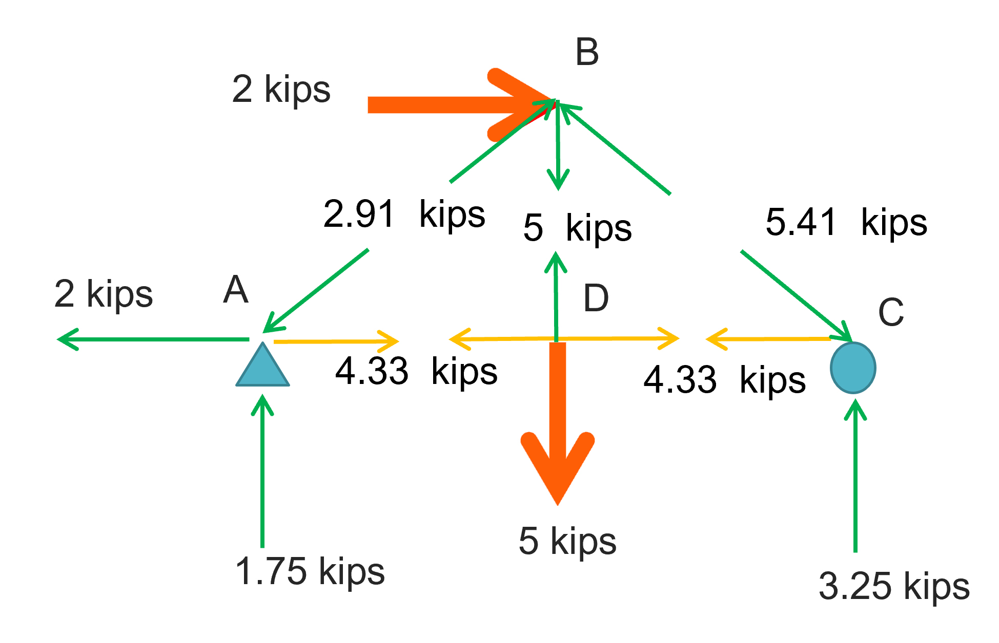
CB = √(CBx2+ CBy2 )=√(4.33)2+(3.25)2 )= 5.41 kips
At the end, the axial forces in truss members are as shown in the diagram below:
3D Trusses – Space frames
Space frames are three-dimensional trusses where members are in tension and compression only. By definition, true trusses should have pinned connections while frames have rigid joints. Space frames may have both pinned and rigid connections. While the topology of space frames may be quite free of regular forms, the half-octahedron and tetrahedron are the common modules for creating a space frame structure.

Figure 5-7: A half-octahedron is one of the common modules for creating a space frame structure (Image source: space frame, 2002, wikipedia)
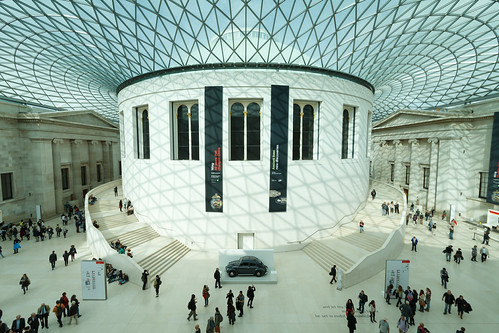
Figure 5-8: The free form of the space frame that covers the British museum courtyard ((Image source: British Museum, 2014, https://www.flickr.com/photos/22087304@N07/15629080951)
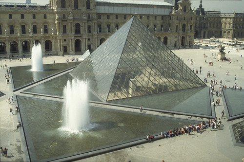
Figure 5-9: The pyramid of the Louvre entrance, designed by Chinese-American architect I. M. Pei, 1984 (Image source: Louvre Project (Pyramid), 1994, https://www.flickr.com/photos/69184488@N06/11876617365)
Space frames are relatively efficient and safe structural systems because even if a few members fail, the forces can reroute to remaining members.
Rule of thumb to determine the proportions of structural components
The economic depth-to-span ratio for steel trusses is 1:10 to 1:20, and for timber trusses is 1:6 to 1:10. The spacing of trusses in roof structures should be 20 to 30 ft for steel structures and 12 to 27 ft for timber trusses. The economic spans of different trusses are shown in the following table.
The suitable depth to span ration of space frames is usually between 1/10 to 1.20 of the span.
Table 5-1: The economic span ratio of trusses [3]

Tensegrities
Video 5-3: What is a tensegrity structure (https://www.youtube.com/watch?v=BzgxYpDyO0M&t=1s)
A tensegrity structure is a stable three-dimensional space frame assembly of continuous cables and discontinuous struts where the struts do not touch one another. In tensegrity structures, tension elements stabilize the compression elements. One of the natural examples of tensegrity structures is the human body, where muscles (the tension elements) stabilize the compression elements (the bones).
Topics for critical thinking
- The best way to understand how tensegrity structures work is to make a physical model. Let’s get started by watching the following instructional video (https://www.youtube.com/watch?v=DQxNPhR20r0) on making a tensegrity model!
Video 5-4: How to make a tensegrity structure?
- Do you know any implications of tensegrity structures in the building industry?
- Watch the following video (https://www.youtube.com/watch?v=Rxtf5wHXkTA&list=PLKPD9oscWijEdwZFVuGbERolnw2auR1E6&t=778s) from its 11th minute to learn about how pioneers of designing tensegrity structures used symmetry in the design and analysis of spatial structures.
Video 5-5: Using symmetry in the design and analysis of spatial structures
- In the following video (https://www.youtube.com/watch?v=U2lKx_FYXWo&list=PLKPD9oscWijEdwZFVuGbERolnw2auR1E6), Professor Ken’ichi Kawaguchi, Architecture Professor at the University of Tokyo discusses the challenges of tensegrity construction. Move to the 11th minute to learn more about his findings.
Video 5-6: Challenges of tensegrity construction
