7 Material Properties
Anahita Khodadadi
In the previous chapters, we have discussed the determination of internal forces produced in structural members by externally applied loads. In chapters 7 and 8, we will discuss the relationship between loads applied to a non-rigid body and the resulting internal forces and deformations induced in the body. These analyses will be used to determine the required size of a structural element to safely resist external loads.
Stress and strain
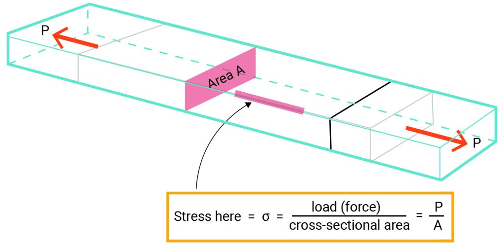
Stress is a term that is used to describe the intensity of a force. By definition, stress is force per unit area of a material and may be described in psi (pounds per square inch), psf (pounds per square foot), MN/m2 (Meganewton per square meter), kgf/cm2 (kilogram-force per square centimeter), MPa (megapascal = N/mm2). Therefore, the axial stress can be represented mathematically via the following equation:
[latex]σ =\frac{P}{A}[/latex]
Where:
Stress = σ = load/area = P/A
P = tensile/compression load or force
A = the area

Figure 7-1: Stress is force per unit area of a material
Any structural member under load has some amount of deformation. The member may be compressed or stretched due to a compression or tension force. Some materials such as steel do deform as well, even though their deformation is not significant. We measure this deformation per unit length and call it strain.
[latex]ε =\frac{D}{L}[/latex]
Where:
Strain = ε= deformation/original length = D/L
D = deformation
L = original length

Figure 7-2: Any structural member under load has some amount of deformation or change of shape. Strain is the deformation per unit length
Modulus of elasticity
When a structural element is stretched on a molecular scale, the molecules are pulled apart. The electromagnetic bond among the molecules resists against the externally applied force and creates the elastic behavior of the element. In the late 17th century, Robert Hooke was the first fellow who discovered that there is a relation between the stress in an element and the developed strain. However, this relationship was formulated by Thomas Young in the 19th century. The relationship between stress and strain is a measure of the elasticity of the material and is called Young’s Modulus or the Modulus of Elasticity (E).
[latex]E=\frac{σ}{ε}[/latex]
Where:
E= Modulus of Elasticity
ε= Strain= deformation/original length = D/L
σ = Stress = load/area = P/A
[latex]E=\frac{σ}{ε}=\frac{P/A}{D/L}=[/latex]
[latex]E=\frac{PL}{AD}=[/latex]
Structural elements cannot deform infinitely and should snap back when the load is removed. All structural materials are elastic to some extent; however, their behaviors during and after applying the load are different. To study the elasticity of a material, we can test its sample in tension and compression and measure their elongation. When a load is progressively added to stretch the material, we measure the load magnitude at the same time as the amount the sample stretches.
Video 7-1: Material properties and fundamental terms used to define them (https://www.youtube.com/watch?v=BHZALtqAjeM)
During this test, you can see that there is a stress limit before which the material returns to its original shape if the load is removed. But beyond that stress limit, the material does not snap back, and the deformation will remain permanent. This stress limit is called the yield stress, and the corresponding elongation is called inelastic or plastic deformation. Then, there is a stress limit, called ultimate stress, where the maximum load can be placed before the breaking of the element. Finally, beyond the ultimate stress, the element deforms rapidly and breaks at the point of fracture.

Figure 7-3: A stress-strain plot of a material
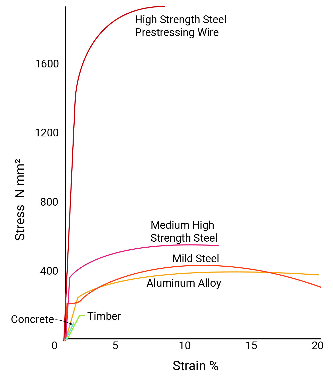
The stress-strain diagram is unique for any given material. Young’s modulus represents a measure of the stiffness of the material. Thus, the slope of the straight line varies greatly for different materials. When a material is referred to as "flexible,” this just means a material has a low Young’s modulus. Moreover, when some materials exceed their yield point, they may crack or suddenly break into pieces. They may not have any plastic deformation, and or their plastic range is remarkably limited. These materials are brittle. In contrast, some materials such as low-carbon steel, aluminum, or copper have a significant plastic range that can warn of impending failure. This type of material behavior is termed ductile.

Figure 7-4: Using stress-strain graph to compare properties of different materials
Video 7-2: Understanding Young's modulus (https://www.youtube.com/watch?v=DLE-ieOVFjI&feature=emb_logo)
Example
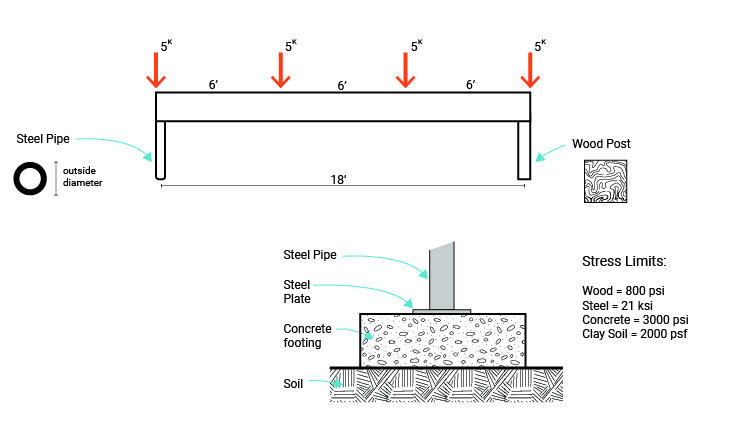
What is the minimum required cross-sectional area for the two columns supporting the beam shown below?
Allowable stress:
Wood = 800 psi
Steel = 21 ksi
Concrete = 3000 psi
Clay Soil = 2000 psf
* Allowable stress is the maximum stress (tensile, compressive, or bending) that is allowed to be applied on a structural material. Building codes generally define the allowable stresses, which for steel and aluminum are fractions of their yield stress.

Σ Fx = 0
Σ Fy = 0 All vertical forces must balance out to zero.
R1+R2-5-5-5-5=0
R1+R2=20
We have a symmetric loading condition. So R1=R2
R1=R2 = 20/2 = 10 k
[latex]Allowable stress: σ =\frac{P}{A}[/latex]
For wood column :
800 = 10,000 / A => A = 10,000 / 800 = 12.5 in2 of wood
Each side should be greater than √12.5=3.54
For steel column
21,000 = 10,000 / A => A = 10,000 / 21,000 = 0.48 in2 of steel
Concrete Allowable stress σ = P / A
3000 = 10,000 / A => A = 10,000 / 3000 = 3.33 in2 steel base plate
Soil Allowable stress σ = P / A
2000 = 10,000 / A => A = 10,000 / 2,000 = 5 ft2 of footing surface
Topics for critical thinking
- How can we use [latex]Allowable stress: σ =\frac{P}{A}[/latex] for calculating the shear stress in structural elements?
- Test a rubber band and find its Young's Modulus. You may watch this video (https://www.youtube.com/watch?v=aGS_tYML3HQ) to learn about similar experiments.
https://www.youtube.com/watch?v=aGS_tYML3HQ
Video 7-3: Determining Young's modulus of a material
