Load Tracing
Previous chapters have discussed loads as they pertain to the major structural elements of beams and columns and this chapter will discuss the structural systems as a whole.
Analysis of the paths along which the loads travel throughout a structural system to reach the ground is called load tracing. This chapter discusses the systematic process of determining loads and support reactions of structural members as they affect the loading condition of other structural elements.
Load Path
- Flooring spans between joists
- Joists span between beams
- Beams span between girders
- Girders span between columns
- Columns carry load to the foundation system and then to the ground
Every time the load travels from one element to another, a support condition should be determined, and the loads and reactions at each transfer should be analyzed.
Tributary area
Each member is associated with an area that can be used to find the total load on that member. The tributary area is an area that corresponds to the load on a member. The following image shows a deck under a uniformly distributed live load. The deck is supported in three different ways: by bearing walls, joists and load-bearing walls, and a combination of joists, beams, girders, and columns. In each case, you can see the tributary area of the supporting walls and joists.
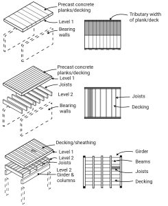
Figure 12-1: Tributary area of beams and joists in a simple deck system
The tributary area of one-way concrete slabs is calculated by splitting the slab area across the direction of steel reinforcements. In two-way concrete slabs, the tributary area divides at 45° from the corners.

Figure 12-2: The tributary area of a one-way concrete slab vs. a two-way concrete slab
Example 1
The image below shows a one-way roof system with an area of 24×20 ft2 . The roof system is composed of two girders, seven beams, and a 4-in thick concrete deck.
First, find the tributary area of Beam-1 and Beam-2.
Second, if:
Floor Live load = 40 psf
The weight of each beam is 31 plf
Weight of 1 cubic foot of the concrete = 150 lbs,
what type of and how much load do Beam-1, Beam-2, Girder-1 carry?
Third, four timber columns hold the roof system, and the allowable stress of the timber is 5000 psf, find the required cross-sectional area of a column using the following equation:
Allowable stress = P/A
Fourth, if the soil load-bearing capacity is 2000 psf, find the required surface area of the footing.
*Note: Assume the columns and foundation are weightless.

Solution:
Tributary area Beam-1 = 2×20 = 40 ft2
Tributary area Beam-2 = 4 × 20 = 80 ft2
Dead load of deck = 150 ×(4”)/12 = 50 psf
Beam-1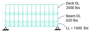
Live load = 40 psf × 40 ft2 = 1600 lbs
DL of beam weight = 31 plf × 20 = 620 lbs
DL of deck = 50 psf × 40 ft2= 2000 lbs
Beam-2
Live load = 40 psf × 80 ft2 = 3200 lbs
DL of beam weight = 31 plf × 20 = 620 lbs
DL of deck = 50 psf × 80 ft2 = 4000 lbs
Girder -1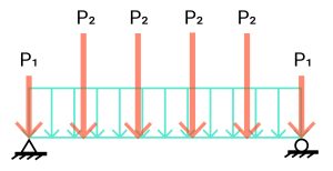
DL of beam weight = 31 plf × 24 = 744 lbs
Live load and DL of the deck are applied to Girder-1 via point loads P1 and P2.
P1 = end reaction in Beam-1 = (Total load on Beam-1)/2
= (1600 + 620 +2000)/2 = 4220 lbs/2 = 2110 lbs
P2 = end reaction in Beam-2 = (Total load on Beam-2)/2
= (3200 + 620 +4000)/2 = 7820 lbs/2 = 3910 lbs
Columns
Axial load on a column = (P1×2 + P2×5 + 744)/2 = (2110×2 + 3910 ×5 + 744)/2 = 24514/2 = 12257 lbs
Required cross sectional area A = P/ Allowable stress
A= 12257/5000 = 2.45 ft2
Footing
Soil load bearing capacity = 2000 psf
Footing required cross sectional area A = P/ Allowable stress
A = 12257 / 2000 = 6.12 ft2
Example 2
A concrete slab floor system spans in the directions shown. Find load diagrams for B1, B2, B3, B4, G2, G1.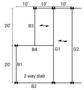
The dead load of the floor slab is 70 psf.
The floor live load is 90 psf.
First, find the tributary area for each beam.
Second, calculate the distribution of the load on the floor.
Third, draw the load diagram for each beam.
Solution:
B1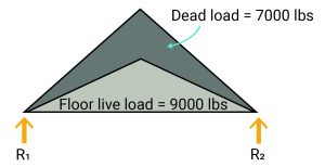
Tributary area = 20×10/2 = 100 ft2
Dead load = 70 psf × 100 = 7000 lbs
Floor Live load = 90 × 100 = 9000 lbs
B2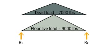
Tributary area = 20×10/2 = 100 ft2
Dead load = 70 psf × 100 = 7000 lbs
Floor Live load = 90 × 100 = 9000 lbs
B3
Tributary area = 20×10/2 = 100 ft2
Dead load = 70 psf × 100 = 7000 lbs
Floor Live load = 90 × 100 = 9000 lbs
R1+R2-7000-9000= 0 R1+R2=16000
R1=R2 (symmetrical loading)
R1=R2 = 8000
B4 
Tributary area = 20×10/2 = 100 ft2
Dead load = 70 psf × 100 = 7000 lbs
Floor Live load = 90 × 100 = 9000 lbs
G1
Tributary area = 40×10/2 + 20×10/2 + 20×10/2
= 200 + 100 + 100 = 400 ft2
Dead load = 70 psf × 400 = 28000 lbs
Floor Live load = 90 × 400 = 36000 lbs
Topics for critical thinking
What are the lateral force-resisting systems? Which of the three main kinds of a braced frame, a shear wall, and a moment-resisting frame is stiffer? Watch the following video (https://www.youtube.com/watch?v=kaKUHU3YYzY&t=1s) to learn about these systems.
Video 12-1: Lateral force-resisting systems
