14
For the control of three-phase motors, magnetic contactors are used to open and close the power contacts in line with the motor. This allows for separation of the control circuit from the power circuit, providing greater safety for the operator and ease and convenience of wiring for the installer. Magnetic contactors also provide low-voltage protection (LVP) in the case of a power outage.
Magnetic contactors must also have built-in overload protection if they are to be used to control motors. The most common controllers for three-phase motors are the across-the-line magnetic starter, meaning that the motor is started with full line voltage.
NEMA vs. IEC
The difference between NEMA and IEC contactors is in their certifications and ratings. NEMA (National Electrical Manufacturers Association) is recognized in North America.
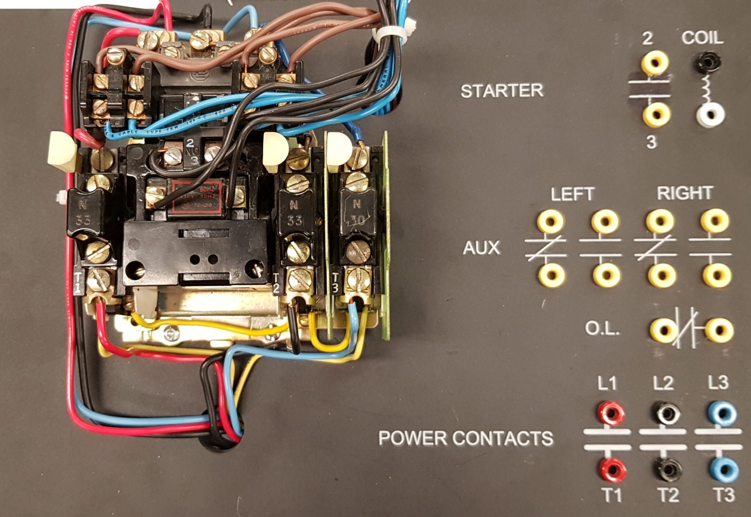
IEC (International electrotechnical commission) is recognized in both North America and Europe.
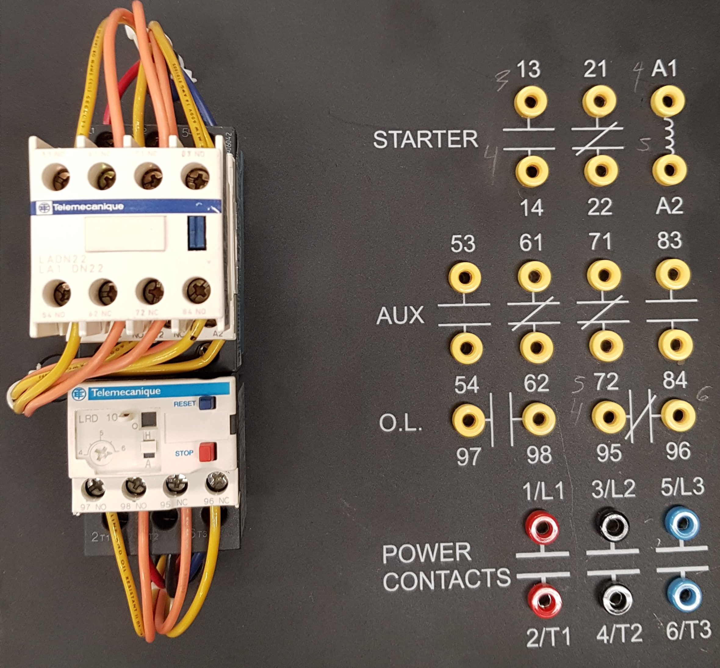
As a general rule, NEMA equipment is more expensive and robust than IEC equipment, but IEC equipment is more versatile. And because is often cheaper, IEC equipment is more commonly seen in modern installations.
Contactor Construction and Operation
A magnetic motor starter has two basic parts: the magnetic contactor and an overload relay.
The magnetic contactor is a solenoid relay consisting of stationary contacts that are wired in series with the lines to the motor, an inductive coil wrapped around a magnetic core and a movable armature attached to moveable contacts. When an electric current is passed through the coil of wire, a magnetic field is created. This field, in turn, draws the armature towards it, causing the movable contacts to bridge the gap of the stationary contacts and thus energizing the motor. A spring is constantly trying to open the contacts but as long as there is a voltage present at the coil, magnetic forces will overcome the strength of this spring.
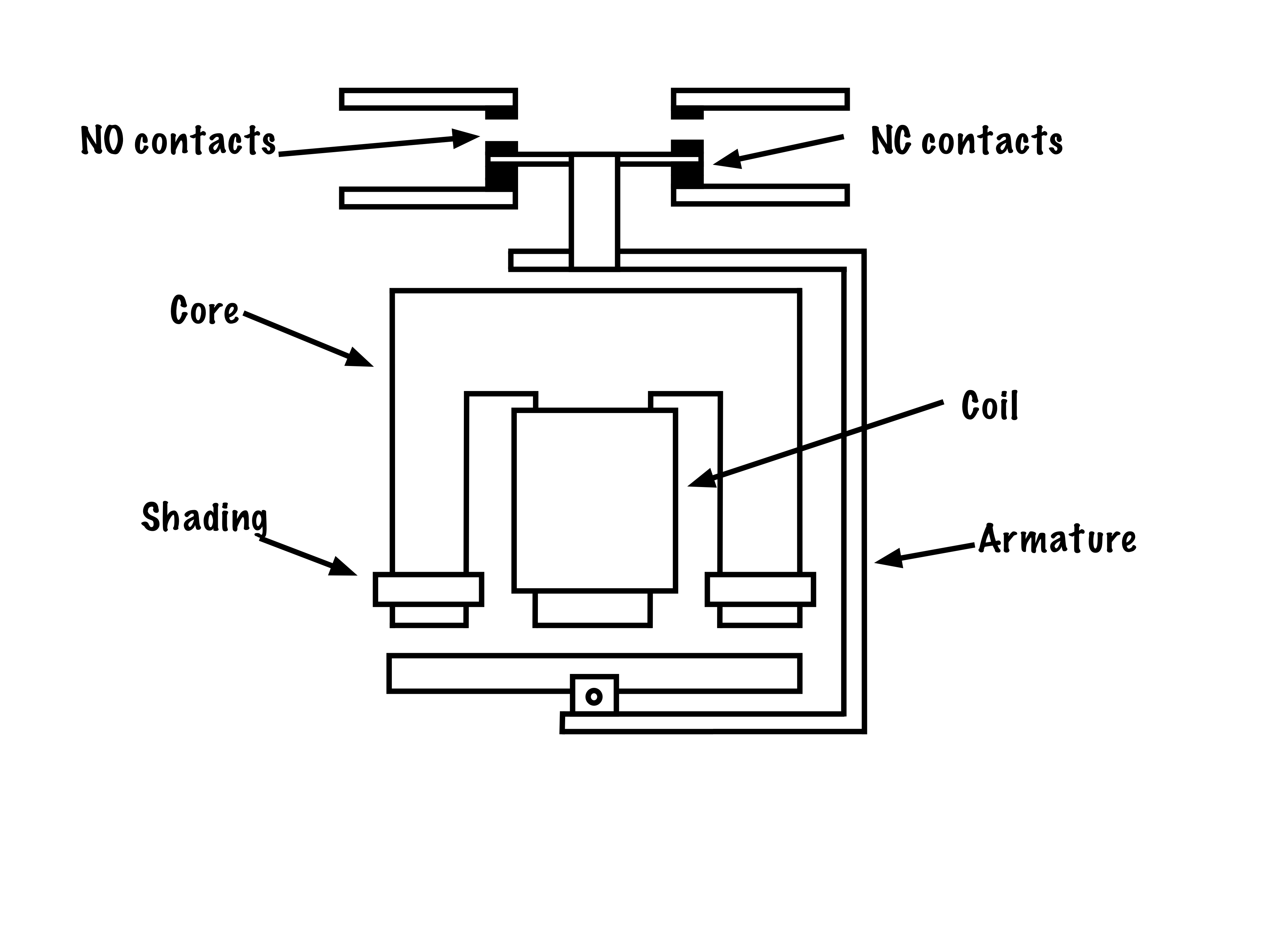
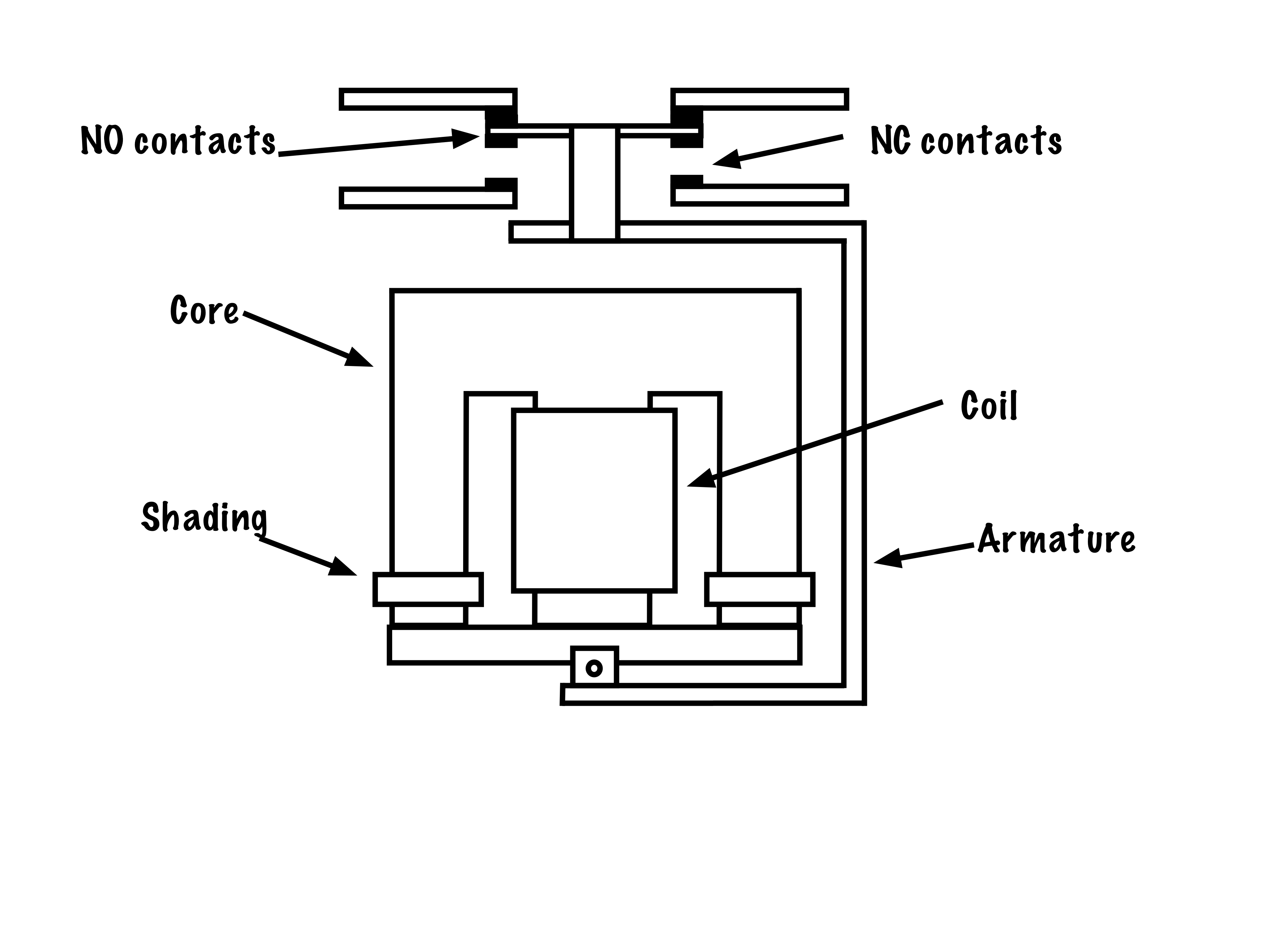
When there is a power outage, however, and the current through the coil drops below a threshold, the spring will push open the contacts. If power is restored, the motor load will not re-energize but will instead require further input from the operator. This type of control is called three-wire control and it provides low-voltage protection (LVP).
For the control of three-phase motors, contactors are built with three sets of horsepower-rated contacts. Additional auxiliary contacts can be included as well. Relay contacts are usually silver-plated to improve their conductivity and although single-break contacts are used, most industrial quality relays use double-break contacts to improve their interrupting capability.
Coils are generally designed to activate at approximately 85% of their rated voltage and will not deactivate until the voltage falls below approximately 85% of the rated value. Usually a coil can withstand an overvoltage of up to 10% without damage to the coil.
Question: If magnetic coils are power by AC, why don’t their contacts open and close 120 times per second?
Answer: Sometimes they do! If a magnetic contactor is making an unnatural “chattering” sound, it may be caused by a loose or faulty shading coil. Shading coils are simple closed loops of conductive material that, when exposed to the changing magnetic field of an AC circuit, creates its own magnetic field with a slight delay in period. This allows for a constant magnetic attraction between the moveable armature and the coil of the contactor. If a contactor is “chattering,” it may need its shading coils repaired or replaced.
The overload relay (OLR) is similar in design to that used in manual motor starters. The key difference is that the normally closed contacts of the OLR are wired in series with the current that flows through the armature of the contactor coil. This ensures that if an overload occurs in any of the three power lines supplying the motor, the normally closed contacts of the OLR will open, and the contactor supplying power to the motor is disconnected from the circuit.
The key utility comes in separating the control circuit from the power circuit. Magnetic-motor starters, for example, can allow the control of a 50 horsepower 600 V three-phase motor (the power circuit) by simply energizing a 120V, 1A load.
This concept of motor starters as a load that controls other larger loads is key to our further understanding of basic motor control.
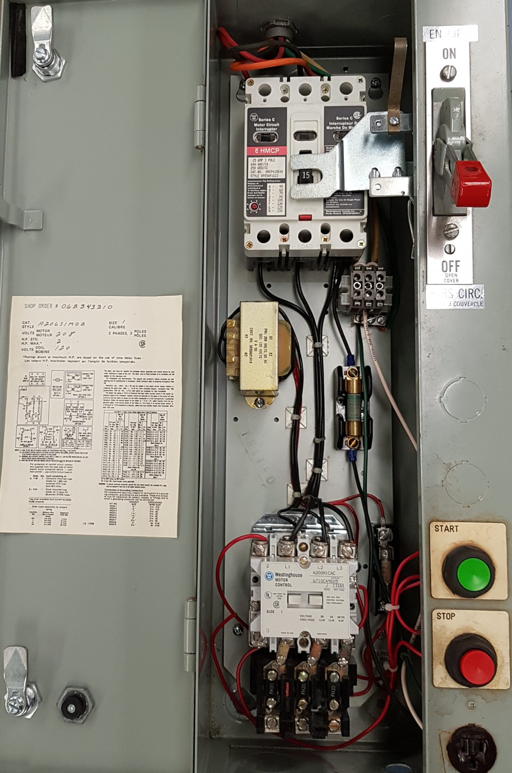
Combination Starters
A combination starter refers to a simplified modular device that contains three-phase disconnects, overcurrent protection, magnetic contactor and overload relays.
In contrast to the Power Circuit, the Control Circuit consists of inputs, in the form of switches, pushbuttons or pilot devices, which when activated, can either directly, or through a magnetic motor starter, energize a load. The Control Circuit often operates at a lower voltage than the Power Circuit for safety and ease of installation.
In contrast to the control circuit, the power circuit provides the large values of voltage and current used by the motor itself. Must be equipped with overcurrent and overload protection, and horsepower-rated contacts in the control gear equal to the voltage and current ratings of the motor.
Circuits with low-voltage protection will not automatically turn back on when voltage is restored following a power outage. Examples include the microwave or power tools.
A device that controls the flow of electrical power to a motor. It is designed to safely start and stop a motor, and provide overload protection.
A heater element paired with normally-closed contacts that open once the heater gets too hot. Two types of relays are the bimetallic strip and the melting solder pot.
In electrical terms, refers to a connection where current has only one path to flow.
Loads connected in series will have the the same value of current flowing through them, and share the total voltage between them. Switches and overcurrent equipment is connected in series with equipment to control and protect it.
With respect to magnetic contactors, the armature or plunger is the movable part of the magnetic circuit. When a coil is energized the armature is pulled in, opening and/or closing a set or sets of contacts.
The difference in electric potential between two points, which is defined as the work needed per unit of charge to move a test charge between the two points. It is measured in volts (V).
A set of contacts that has been designed to make or break the flow of current to a motor and can handle loads up to a specified amount of horsepower at a specific voltage. The size of contacts are determined by the size of the motor they are controlling.
Contacts on a magnetic starter that are not Horsepower rated. Can come as either normally-open or normally-closed and can be used as maintaining contacts, electrical interlocks or control for pilot lights.
A contact that under normal conditions has continuity through it. When the contact changes its state it interrupts the flow of current by opening its contacts. Can be associated with pushbuttons, pilot devices or magnetic contactors.
A moderate and gradual rise in the value of current over a relatively long period of time that is caused by excessive amounts of current drawn by a motor due to too much load being put on the motor.
A sharp and fast rise in current over a short period of time (fractions of a second) where the value of current is far greater than the nominal line current.
